Working method of switching optical path interface mechanism for optical fiber channel of relay protection device

A technology of relay protection device and optical fiber interface, which is applied in the direction of optical fiber transmission, electrical components, coupling of optical waveguides, etc. Attenuation increase and other problems, to achieve the effect of improving the level of on-site protection verification and maintenance, solving the problem of poor contact, and shortening the switching time

Active Publication Date: 2016-06-15
CHANGZHOU POWER SUPPLY OF JIANGSU ELECTRIC POWER +2
View PDF4 Cites 0 Cited by
  • Summary
  • Abstract
  • Description
  • Claims
  • Application Information

AI Technical Summary

Problems solved by technology

The protection of 220kV and above fiber optic channels requires frequent installation and removal of the optical cable connector from the relay protection device during the protection verification test and measurement of optical power, so it is easy to cause the wear of the optical cable interface and the increase in the attenuation of the optical interface contact surface , thereby affecting the accuracy of the relay protection device calibration, and even damage to the optical cable interface will bring hidden dangers to the safe and reliable operation of the main protection of the power line
[0004] At present, the optical fiber protection devices at home and abroad do not have a standard and perfect verification process for the verification of the protection device in the field, especially the verification of the fiber channel.

Method used


Image

  • Working method of switching optical path interface mechanism for optical fiber channel of relay protection device
  • Working method of switching optical path interface mechanism for optical fiber channel of relay protection device
  • Working method of switching optical path interface mechanism for optical fiber channel of relay protection device

Examples


Embodiment Construction

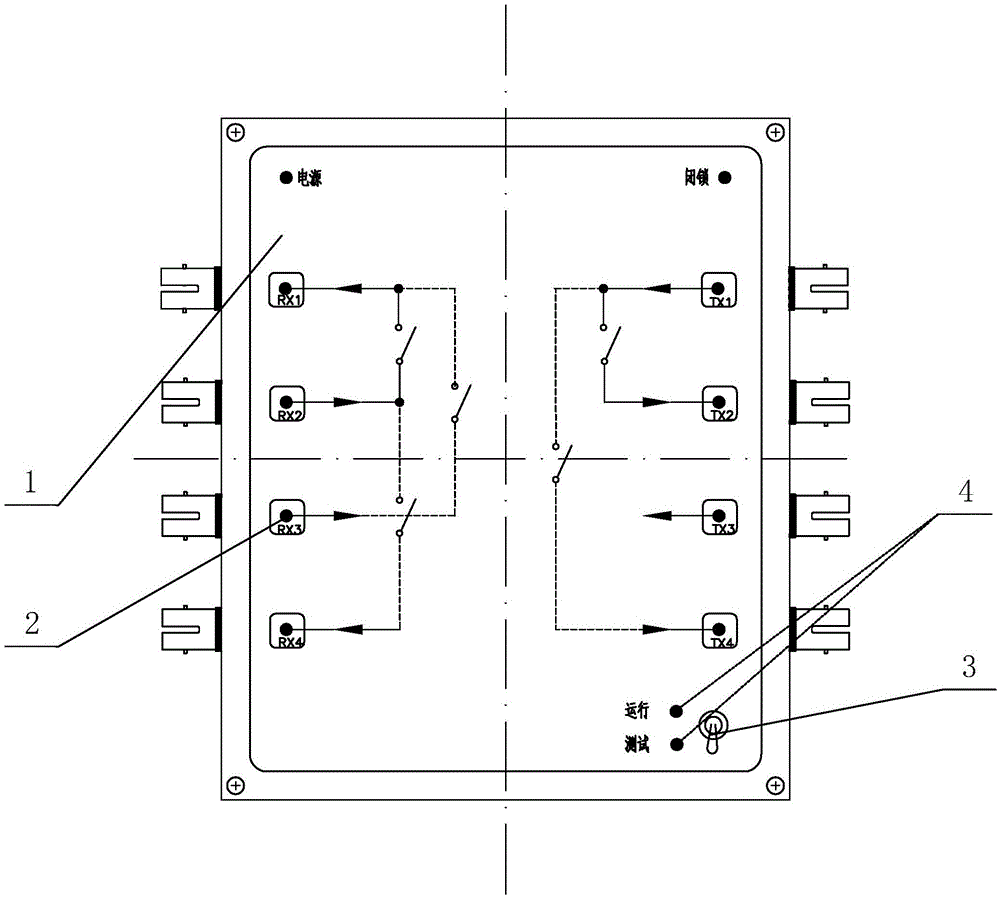
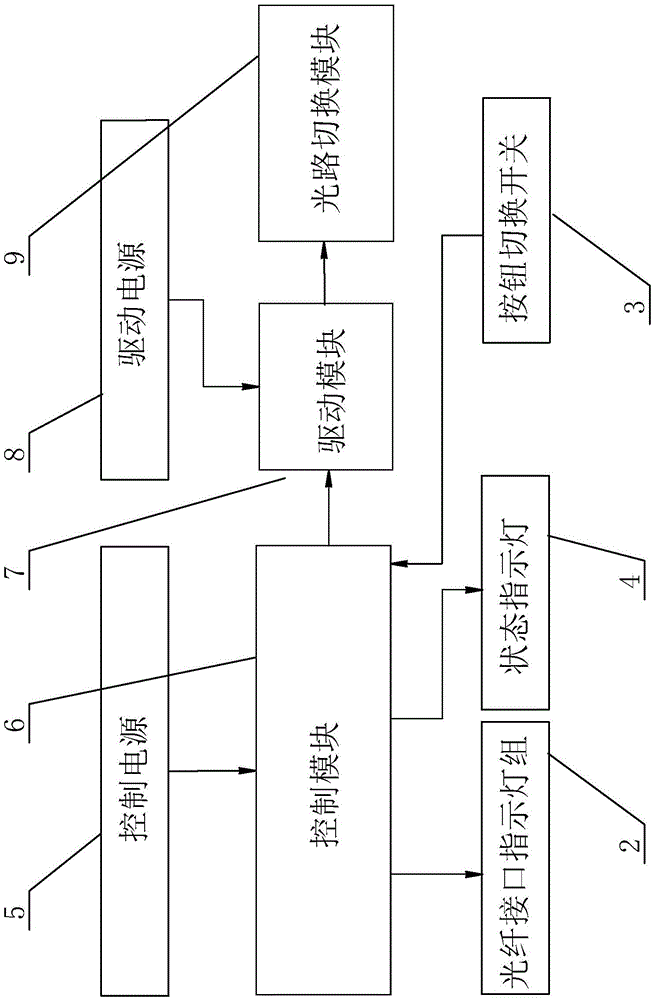
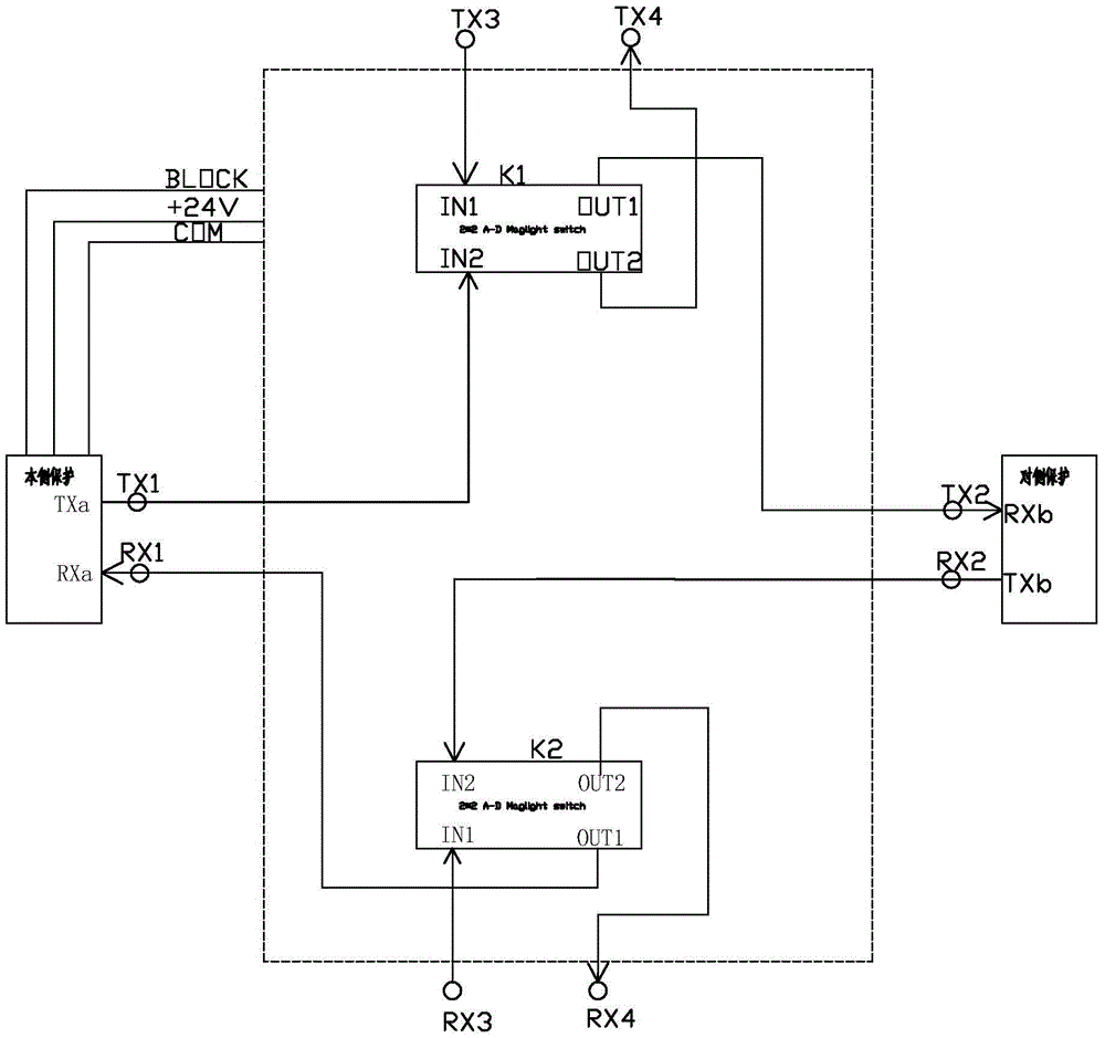
[0019] As shown in Figures 1 to 3, the switching optical path interface mechanism for the fiber channel test of the relay protection device of this embodiment includes a hood 1 and a control module 6 installed in the hood 1, a driving module 7 and an optical path switching module 9 , the control module 6 of the present invention is a complex programmable logic device, the complex programmable logic device is manufactured by Altera Corporation, through the control module 6 to provide the switching signal input by the corresponding conduction optical path switching module 9, the power supply terminal of the control module 6 Be connected with control power supply 5, and this control power supply 5 adopts DC24V, and its power consumption is as little as possible, and the input end of control module 6 is connected with the button switching switch 3 of running state and test state on the panel of installing hood 1, and this button switches The switch 3 is pressed again and again to s...


PUM


Abstract

The invention relates to a working method of an optical path switching interface mechanism for an optical fiber channel test of a relay protection device. According to the optical path switching interface mechanism, the power source end of a control module is connected with a control power source, the input end of the control module is connected with a button change-over switch, and the output end of the control module is connected with a driver module; an optical path switching module comprises two optomagnetic switches, four transmitting optical fiber interfaces and four receiving optical fiber interfaces, wherein the output end of the driver module is connected with the control ends of the two optomagnetic switches, and the input ends and the output ends of the two optomagnetic switches are connected with the corresponding transmitting optical fiber interfaces and the corresponding receiving optical fiber interfaces. The control module provides a control signal corresponding to the connected optical path switching module, a test instrument can be connected with the relay protection device or an optical power meter or an optical attenuator through the optical path switching interface mechanism, then the driver module drives the optical path switching module to carry out optical path switching of the interfaces, and therefore the normal running state and the testing state of a protection test and the optical fiber channel test can be achieved.

Description

[0001] This application is a divisional application of the invention patent application with the application number: 201010502186.2, the invention name is "Switching Optical Path Interface Mechanism for Optical Fiber Channel Test of Relay Protection Device", and the application date is: September 29, 2010. technical field [0002] The invention relates to a working method of a switching optical path interface mechanism for an optical fiber channel test of a relay protection device, and belongs to the technical field of relay protection devices. Background technique [0003] The secondary equipment in the power system is used to monitor, control, adjust, protect the work of the primary equipment, and provide low-voltage electrical equipment required for operating conditions or production command signals for operation and maintenance personnel, and the relay protection mechanism is an important power system secondary circuit equipment. With the gradual promotion of smart subst...

Claims


Application Information

Patent Timeline
Patent Type & Authority Patents(China)
IPC IPC(8): H04B10/075H04B10/25G02B6/35
Inventor 张红洁许箴董祖晨
Owner CHANGZHOU POWER SUPPLY OF JIANGSU ELECTRIC POWER
Why Eureka
Try Eureka