Control method for direct current voltage of grid-side converter of high-voltage doubly-fed power generation system

A grid-side converter, DC voltage technology, applied in the direction of single-grid parallel feeding arrangement, etc., can solve the problems of side power fluctuation, long transient process of doubly-fed wind turbine system, loss of control of the converter network, etc. The effect of suppressing DC voltage instability, avoiding off-grid problems, and improving control margins

Active Publication Date: 2014-09-10
CECEP WIND POWER ZHANGBEI
View PDF5 Cites 7 Cited by
  • Summary
  • Abstract
  • Description
  • Claims
  • Application Information

AI Technical Summary

Problems solved by technology

When the grid voltage drops, the machine-side power of the doubly-fed converter fluctuates significantly, especially for high-voltage doubly-fed generators, the stator resistance is small, when the grid voltage drops, due to the large stator time constant, the doubly-fed wind turbine The transient process of the system is relatively long, and the impact of energy coupled from the rotor side of the high-voltage double-fed generator at the moment of power grid drop and recovery can easily lead to overvoltage on the DC side
Generally used in low-voltage double-fed generators, the converter often uses the DC side Chopper discharge circuit to suppress the DC side overvoltage, but the frequent startup of the Chopper will obviously affect the stability of the DC side. When the DC side fluctuates too much, not only cannot Effectively support the process of the converter side passing through the power grid drop smoothly, and directly lead to saturation of the DC voltage control loop, causing the converter grid side to lose control and protect the shutdown

Method used


Image

  • Control method for direct current voltage of grid-side converter of high-voltage doubly-fed power generation system
  • Control method for direct current voltage of grid-side converter of high-voltage doubly-fed power generation system
  • Control method for direct current voltage of grid-side converter of high-voltage doubly-fed power generation system

Examples


Embodiment Construction

[0017] The present invention will be described in detail below in conjunction with the accompanying drawings and embodiments.

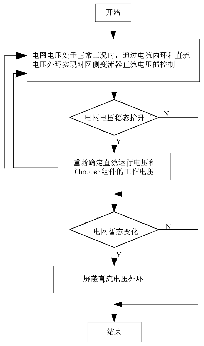
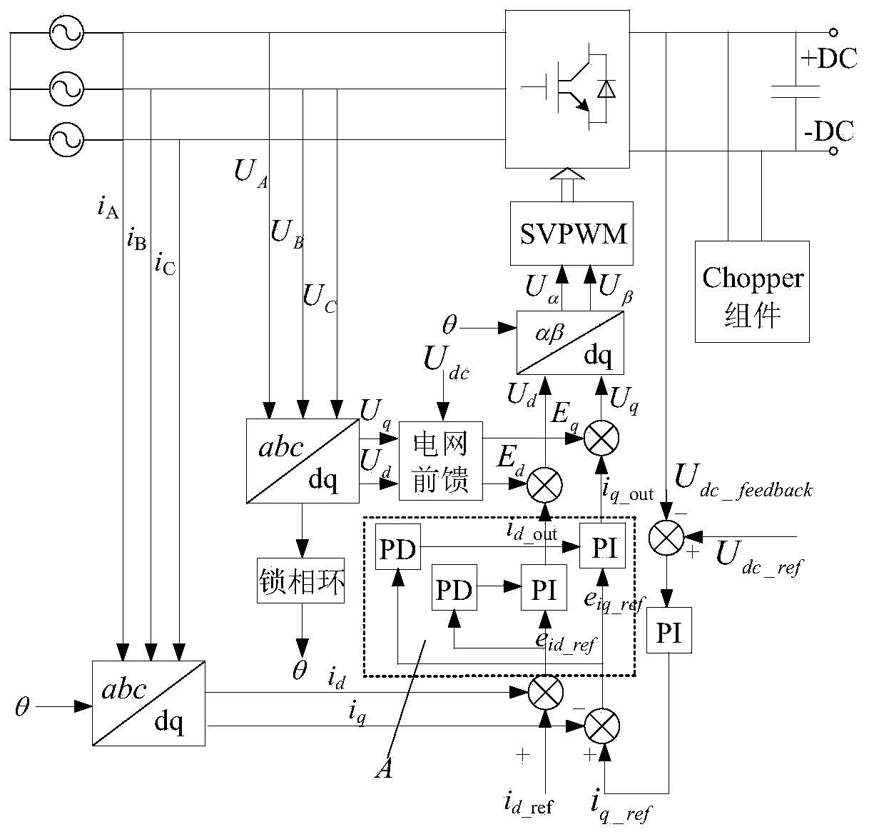
[0018] Such as figure 1 , figure 2 As shown, the present invention provides a method for controlling the DC voltage of a grid-side converter in a high-voltage double-fed power generation system. The method is implemented based on a control module of a grid-side system of a double-fed converter, and includes the following steps:

[0019] 1) When the grid voltage is in normal working condition, the control of the DC voltage of the grid-side converter is realized through the current inner loop and the DC voltage outer loop. The control process is as follows:

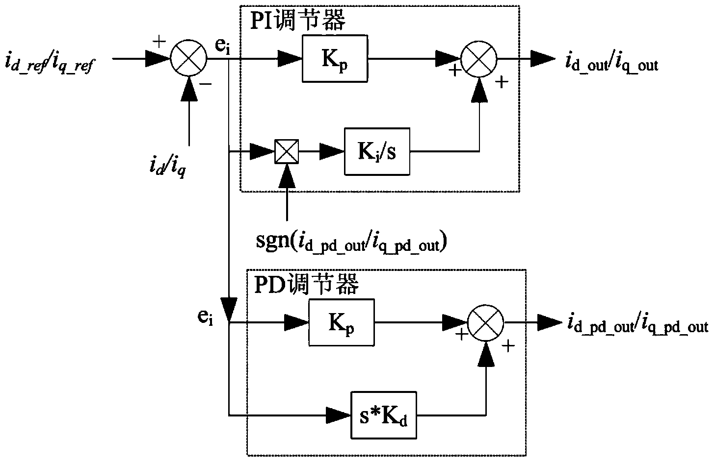
[0020] ①In the DC voltage outer loop, set the DC voltage given value U dc_ref With the feedback value of DC voltage U dc_feedback After the operation, the operation result passes through the PI (Proportional Integral) regulator and outputs the given amount of active current i q_ref , and the g...


PUM


Abstract

The invention relates to a control method for a direct current voltage of a grid-side converter of a high-voltage doubly-fed power generation system. The control method for the direct current voltage of the grid-side converter of the high-voltage doubly-fed power generation system includes the following steps: 1) when a power grid voltage is located at a normal working condition, controlling the direct current voltage of the grid-side converter through an inner current loop and an outer direct current voltage loop; 2) judging whether the power grid voltage rises stably, if not, performing a step 3), if so, re-determining a proper direct current running voltage U'dc-ref and a working voltage of a Chopper component, and using the same control process as that of the step 1) to control the grid-side direct current voltage of the converter; 3) judging whether the power grid voltage appears transient change, if not, ending the control process, if so, controlling the direct current voltage of the grid-side converter through the single close-loop control of current. The control method for the direct current voltage of the grid-side converter of the high-voltage doubly-fed power generation system can be broadly used for controlling the grid-side direct current voltage of the converter.

Description

technical field [0001] The invention relates to a DC voltage control method, in particular to a DC voltage control method of a grid-side converter in a high-voltage double-fed power generation system. Background technique [0002] my country is rich in wind energy resources. With the increasingly prominent non-renewable energy crisis, the wind power industry has made great progress in recent years, and the installed capacity of wind power has continued to increase. Among them, megawatt-level double-fed wind turbines have been applied in many wind farms. Among the currently applied double-fed wind turbines, the rated output voltage of generators ranging from 1.5MW to 3.0MW is 690V. Compared with the capacity of the generator set, too small output voltage means relatively large output current , which puts relatively high requirements on the electromagnetic design and production process of the doubly-fed generator, and at the same time, the excessive current also means that the...

Claims


Application Information

Patent Timeline
Patent Type & Authority Applications(China)
IPC IPC(8): H02J3/38
Inventor 李群星赵站伟崔凯
Owner CECEP WIND POWER ZHANGBEI
Why Eureka
Try Eureka