
Concentric diverter spool

A diverter valve, concentric valve technology, applied in multi-port valves, valve devices, instruments, etc., can solve the problem of not being able to set the temperature

Inactive Publication Date: 2017-01-11
KOHLER CO
View PDF5 Cites 0 Cited by
  • Summary
  • Abstract
  • Description
  • Claims
  • Application Information

AI Technical Summary

Problems solved by technology

This leads to the fact that the desired temperature cannot be set (e.g. by turning the inner concentric turntable) before the volume flow has been set (e.g. by turning the outer turntable)

Method used


Image

  • Concentric diverter spool
  • Concentric diverter spool
  • Concentric diverter spool

Examples


Embodiment Construction

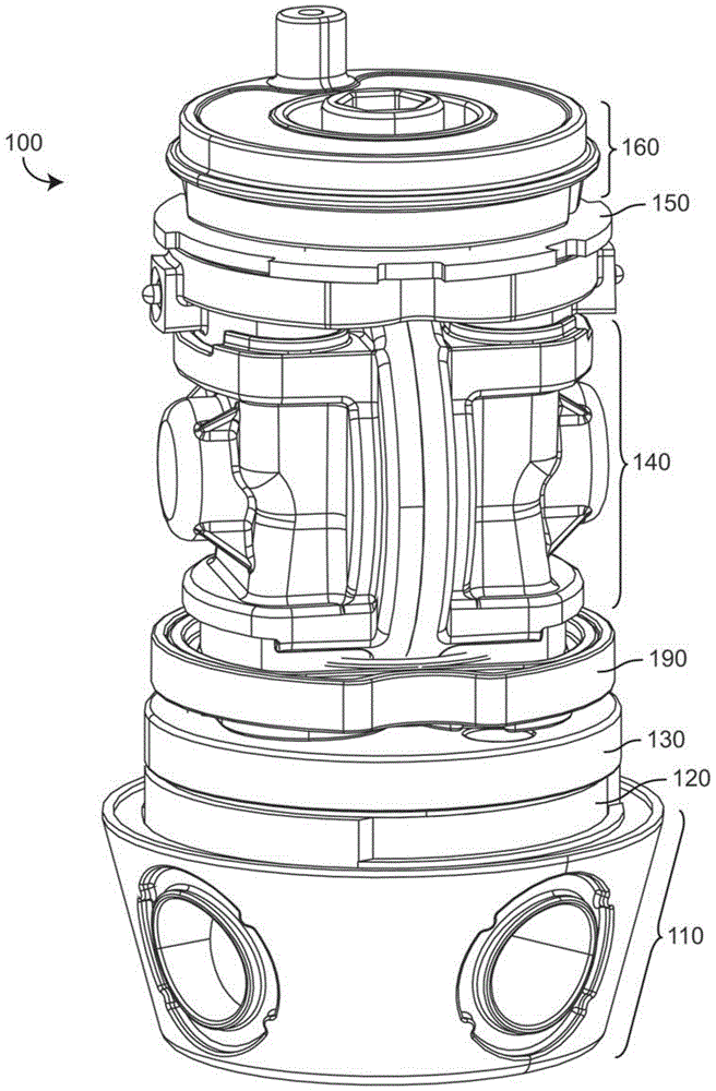
[0047] Referring generally to the drawings, a concentric diverter cartridge and components thereof are shown in accordance with exemplary embodiments. Before further discussing the details of the concentric diverter spool and / or its components, it should be noted that references in this specification to "front", "back", "rear", "top", "bottom", "upper", "lower" , "inner", "outer", "right" and "left" are used only to indicate the orientation of various elements in the drawings. These terms are not intended to limit the elements they describe, as various elements may have different orientations in various applications.

[0048] It should also be noted that in this specification, the term "coupled" means that two components are directly or indirectly connected to each other. Such connections may be substantially fixed or substantially movable, and / or such connections permit fluid flow, transmission of forces, stresses, torques, or other interactions between the connected compone...


PUM


Abstract

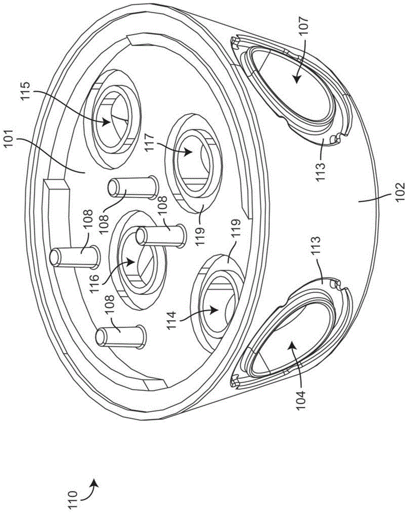
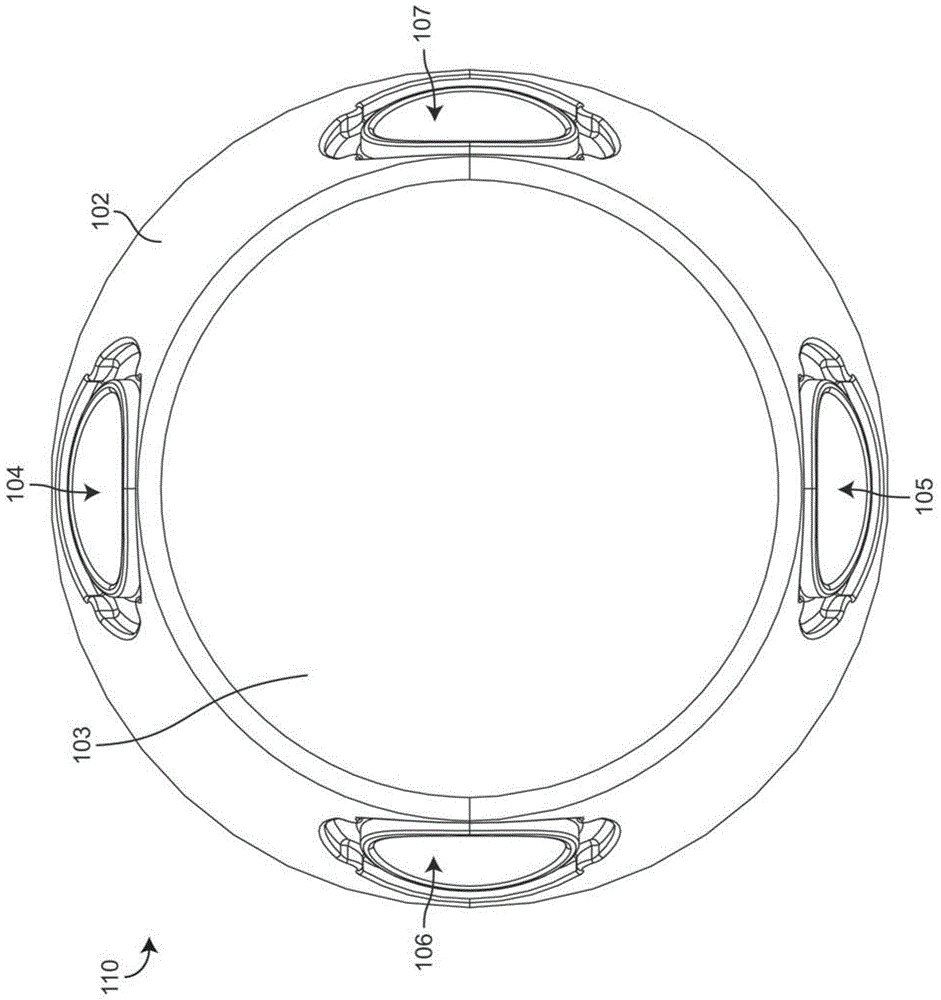
A diverter spool for a fluid mixing valve includes an inlet fitting having a first inlet port, a second inlet port, a first outlet port, and a second outlet port. The spool also includes a diverter plate having a first inlet passage and a second inlet passage. The diverter plate is rotatable relative to the inlet fitting between a first end position, a second end position and an intermediate position, the intermediate position being between the first end position and the second end position. Rotation of the diverter plate from the neutral position toward the first end position increases volumetric flow through the spool and directs fluid to the first discharge port. Rotation of the diverter plate from the neutral position toward the second end position increases volumetric flow through the spool and directs fluid to the second discharge port.

Description

Background technique [0001] The present invention relates generally to the field of valve assemblies for fluid control devices, and more particularly to valve assembly spools for controlling fluid volume and fluid temperature. [0002] Valve assemblies are used in various plumbing fixtures to control the temperature and volume of water dispensed from the fixture. The valve assembly can receive hot and cold water from separate supply lines and controllably mix the water to provide an output having an intermediate temperature. [0003] The sequential valve assembly uses a single handle which, when rotated, opens the valve and increases the volumetric flow to maximum flow of cold water. Continuous rotation of the handle maintains volume flow while increasing temperature. [0004] Other valve assemblies use two concentrically mounted handles or dials, one for temperature control and one for volumetric flow. Such valve assemblies are often referred to as "concentric" valves. A ...

Claims


Application Information

Patent Timeline
Patent Type & Authority Patents(China)
IPC IPC(8): F16K11/074F16K11/20
CPCF16K11/074F16K11/20F16K11/0743G05D23/1313Y10T137/86863F16K11/00
Inventor D·J·布劳尔M·A·尼韦尔
Owner KOHLER CO
Learn More