Lead bending device for expanding or reducing lead width
What is AI technical title?
AI technical title is built by PatSnap AI team. It summarizes the technical point description of the patent document.
A bending device and pin technology, applied in the field of network transformer manufacturing equipment, to achieve the effect of accurate spacing deformation and simple structure
Inactive Publication Date: 2016-01-13
ZHONGJIANG KAIXUN ELECTRONICS
View PDF7 Cites 0 Cited by
Summary
Abstract
Description
Claims
Application Information
AI Technical Summary
This helps you quickly interpret patents by identifying the three key elements:
Problems solved by technology
Method used
Benefits of technology
Problems solved by technology
[0006] In order to solve the above-mentioned problems, the pin bending device suitable for expanding or reducing the pin width provided by the present invention solves the problem through the following technical points: the pin bending device suitable for expanding or reducing the pin width includes a frame, The pressing bar arranged on the frame, the deformed pressing block fixed on the lower end of the pressing bar and the material platform located under the deformed pressing block, the pressing bar can move along its axial direction, and the pressing bar is also fixed with pin tight fixed device;
Method used
Image
Click on the blue label to locate the original text in one second.
Reading with bidirectional positioning of images and text.
Examples
Embodiment 1
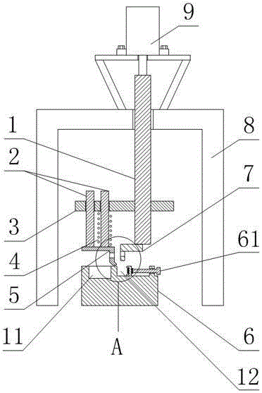
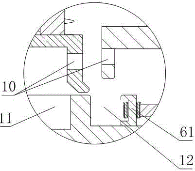
[0028] Such as Figure 1 to Figure 3 As shown, the pin bending device suitable for expanding or reducing the pin width includes a frame 8, a pressing bar 1 arranged on the rack 8, a deformation pressing block 7 fixed on the lower end of the pressing bar 1 and a deformation pressing block located at the bottom of the pressing bar 1. 7 below the material platform 6, the pressure rod 1 can move along its axial direction, and the pressure rod 1 is also fixed with a pin tightening device;
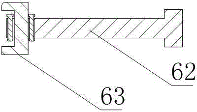
[0029] The pin tightening device comprises a spring seat 3, a spring 4 and a positioning pressing block 5, the spring seat 3 is fixed on the pressing bar 1, and the two ends of the spring 4 are fixedly connected with the spring seat 3 and the positioning pressing block 5 respectively, and the spring The axis of 4 is parallel to the axis of pressure rod 1, and the lower end position of positioning briquetting block 5 is lower than the lower end position of deformed briquetting block 7;
[0030] ...
Embodiment 2
[0036] The present embodiment is further limited on the basis of embodiment 1, as Figure 1 to Figure 3 As shown, in order to drive the pressing rod 1 conveniently, the upper end of the pressing rod 1 is also fixedly connected with a pressing rod driving part. According to the size of the workload, the set pressure rod driving part can be set in the structural form of artificial compressive stress drive or hydraulic pressure or air pressure drive.
[0037] In order to facilitate the working efficiency of the present invention, facilitate switching of working states and simplify the structure of the pressing rod driving part, the pressing rod driving part is an air cylinder 9 .
Embodiment 3
[0039] The present embodiment is further limited on the basis of embodiment 1, as Figure 1 to Figure 3 As shown, in order to prevent the positioning pressing block 5 from being skewed relative to the deformed pressing block 7 after the interaction force is generated with the pins, it also includes a guide rod 2, the axis of the guide rod 2 is in line with the The axes of the spring 4 are parallel, the lower end of the guide rod 2 is fixedly connected with the positioning pressure block 5 , and the spring seat 3 is also provided with a hole which is loosely matched with the guide rod 2 .
[0040] In order to enhance the ability to limit the movement direction of the positioning pressure block 5 and prevent the uneven deformation of the spring 4, there are more than one guide rod 2, and one of the guide rods 2 is located in the inner ring of the spring 4.
PUM
Abstract
The invention discloses a pin bending device suitable for expanding or narrowing the width between pins. The pin bending device comprises a rack, a press rod, a deformation press block fixed at the lower end of the press rod, and a material table positioned under the deformation press block, wherein the press rod can move along the axial direction; a pin locking device is also fixed on the press rod; the pin locking device comprises a spring seat, a spring and a locating press block; the spring seat is fixed on the press rod; the two ends of the spring are respectively and fixedly connected with the spring seat and the locating press block; the axis of the spring is parallel to that of the press rod; the position of the lower end of the locating press block is lower than that of the lower end of the deformation press block; the locating press block and the deformation press block are respectively provided with a containing hole; the material table is also provided with a groove adjusting part; a groove is formed between the groove adjusting part and the material table. The pin bending device is simple in structure; after the pin bending device is used, the condition that the matching accuracy between the pins and pin holes are not high due to the change of gaps between the pins caused by bending processing can be avoided; the pin bending device is suitable for expanding or narrowing the width between the pins.
Description
technical field [0001] The invention relates to the field of equipment used in the manufacture of network transformers, in particular to a lead bending device suitable for enlarging or reducing the width of the leads. Background technique [0002] Network transformers are widely used in high-performance digital switches; SDH / ATM transmission equipment; ISDN, ADSL, VDSL, POE power receiving equipment integrated business digital equipment; FILT optical fiber loop equipment; Ethernet switches and other equipment. [0003] The network transformer mainly includes a base, a cover, pins, and coils arranged between the pins. At the same time, the pins on the network transformer are generally arranged in two rows. In the prior art, the pins on the packaged network transformer are mostly needle-shaped. However, in practical applications, since the pin holes configured for the pins have different widths, it is often necessary to bend the pins to change the width between two rows of pin...
Claims
Application Information
Patent Timeline
Application Date:The date an application was filed.
Publication Date:The date a patent or application was officially published.
First Publication Date:The earliest publication date of a patent with the same application number.
Issue Date:Publication date of the patent grant document.
PCT Entry Date:The Entry date of PCT National Phase.
Estimated Expiry Date:The statutory expiry date of a patent right according to the Patent Law, and it is the longest term of protection that the patent right can achieve without the termination of the patent right due to other reasons(Term extension factor has been taken into account ).
Invalid Date:Actual expiry date is based on effective date or publication date of legal transaction data of invalid patent.

