System and method for detecting surface defects of large-caliber spherical optical element

A technology of spherical optics and detection system

Active Publication Date: 2014-12-17
ZHEJIANG UNIV
View PDF7 Cites 35 Cited by
  • Summary
  • Abstract
  • Description
  • Claims
  • Application Information

AI Technical Summary

Problems solved by technology

[0003] The traditional inspection method for spherical optical components is mainly the visual method, which is greatly affected by the proficiency of the inspected person and is highly subjective. Moreover, long-term inspection will cause human eye fatigue, and at the same time, it cannot give a picture of the defects. Quantitative description of information

Method used


Image

  • System and method for detecting surface defects of large-caliber spherical optical element
  • System and method for detecting surface defects of large-caliber spherical optical element
  • System and method for detecting surface defects of large-caliber spherical optical element

Examples


Embodiment

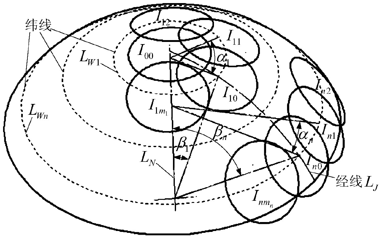
[0079] A surface flaw detection test was carried out on the surface of a large-aperture spherical optical element. During the inspection, the selected large-aperture spherical optical element to be tested has a caliber of φ160mm, a spherical curvature radius R of 200mm, and a detection microscope with a field of view of f s It is φ15mm. Under the constraints of invariant rules along the latitude, the sub-aperture distribution is planned according to the trajectory of the latitude and longitude. During planning, the overlapping area between the sub-apertures in the latitude direction is f s / 4, take the overlap coefficient k=1.1 in the meridian direction, then the distribution of each sub-aperture on the spherical surface can be calculated according to formula 3, and obtained after three-dimensional simulation Image 6 The subaperture planning image shown. A total of 63 sub-apertures are planned. As can be seen from the figure, the sub-apertures are evenly distributed and co...


PUM


Abstract

The invention discloses a system and method for detecting surface defects of a large-caliber spherical optical element. The system comprises an XY two-dimensional guide rail, a two-dimensional rotating system, a large-caliber spherical optical element, an annular illuminating light source, a Z-direction guide rail, a microscope, a CCD1, an optical auto-collimating centering instrument and a CCD2, wherein the large-caliber spherical optical element is fixedly arranged on the two-dimensional rotating system; the two-dimensional rotating system is arranged on the XY two-dimensional guide rail, so that multi-axis linkage of the large-caliber spherical optical element is realized; the CCD1 is connected to the microscope and is fixedly arranged on the annular illuminating light source; the annular illuminating light source and the optical auto-collimating centering instrument are fixedly arranged on the Z-direction guide rail and are in translational motion along with the Z-direction guide rail along the Z-axis direction; and the CCD2 is connected to the optical auto-collimating centering instrument. According to the invention, the subaperture sampling process of the surface defects of the large-caliber spherical optical element is realized, and full-caliber defect gray level images are subjected to digital feature extraction, so that automatic quantitative determination of the defects is realized.

Description

technical field [0001] The invention belongs to the technical field of machine vision detection, and relates to a large-diameter spherical optical element surface defect detection system and a method thereof. Background technique [0002] Large-aperture spherical optical elements are widely used in large-aperture space telescopes and ICF (inertial confinement fusion) target chamber terminal systems. Defects on the surface of the elements, such as pits and scratches, will affect the imaging quality and generate unnecessary noise. Scattering and diffraction cause energy loss, which may also cause secondary damage due to excessive energy in high-power ICF systems. Therefore, it is necessary to detect surface defects of large-aperture spherical optical components before using them, and digitize them. Evaluate defect information to provide a reliable numerical basis for the use of large-aperture spherical optical components. [0003] The traditional inspection method for spheric...

Claims


Application Information

Patent Timeline
Patent Type & Authority Applications(China)
IPC IPC(8): G01N21/958
Inventor 杨甬英刘东曹频李阳李璐
Owner ZHEJIANG UNIV
Why Eureka
Try Eureka