Method for evaluating surface defects of spherical optical components

A spherical optics and defect evaluation technology, applied in the direction of using optical devices, material analysis through optical means, scientific instruments, etc., can solve the problems of inability to give quantitative description of defect information, human eyes fatigue, etc., to improve detection efficiency and The effect of detection accuracy and reliable numerical basis

Active Publication Date: 2015-11-25
ZHEJIANG UNIV +1
View PDF6 Cites 18 Cited by
  • Summary
  • Abstract
  • Description
  • Claims
  • Application Information

AI Technical Summary

Problems solved by technology

[0003] The traditional detection method for spherical optical component defects is mainly the visual method, which uses strong light to illuminate the spherical surface, and the human eye uses reflected light and transmitted light to observe from different directions. The visual method is greatly affected by the proficiency of the inspector, and subjectivity Strong, and long-term detection will cause human eye fatigue, and at the same time cannot give a quantitative description of defect information

Method used


Image

  • Method for evaluating surface defects of spherical optical components
  • Method for evaluating surface defects of spherical optical components
  • Method for evaluating surface defects of spherical optical components

Examples


Embodiment 1

[0054] Below, embodiment 1 of the present invention will use Figure 1-9 to describe in detail.

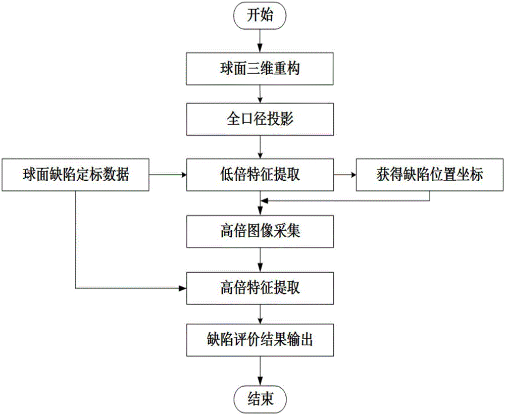
[0055] The method for evaluating the surface defect of a spherical optical element specifically includes the following steps:

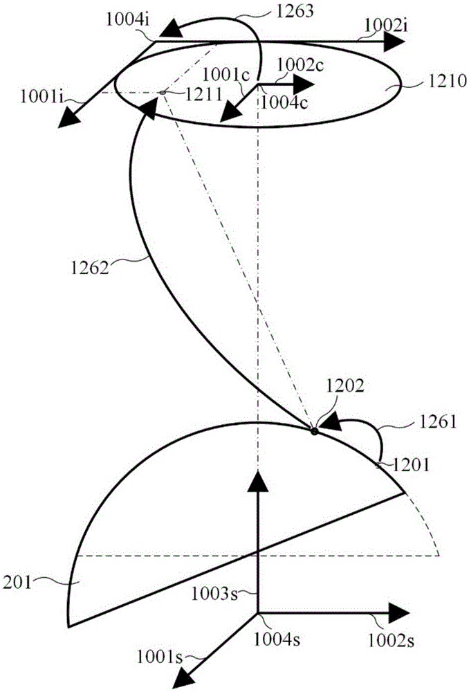
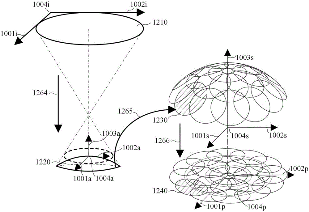
[0056] Step 1. When the spherical optical element 201 is imaged on the image plane through micro-scattering dark field imaging, the obtained imaging sub-aperture image is a two-dimensional image. Since information compression along the optical axis of imaging occurs during the optical imaging process, three-dimensional reconstruction of the spherical surface must first be performed to correct the information compression along the optical axis of imaging caused by surface defects of the spherical optical element 201 through optical imaging.

[0057] Step 2. The three-dimensional sub-aperture image is obtained after three-dimensional reconstruction of the spherical surface. In order to facilitate feature extraction, the information of the three-dimensional...

Embodiment 2

[0095] Below, embodiment 2 of the present invention will combine Figure 10 to describe in detail. In Example 2, a method of evaluating a surface defect of a spherical optical element when evaluating a small-diameter spherical optical element will be described.

[0096] The characteristic of the small-aperture spherical optical element 1801 discussed in this embodiment is that it only needs to perform micro-scattering dark-field imaging on a sub-aperture at the vertex of the sphere to obtain full-aperture imaging of the entire surface of the small-aperture spherical optical element. Therefore, the corresponding defect evaluation method is also simpler than that in Embodiment 1, and the spherical defect information can be obtained by processing the sub-aperture image through image processing and defect calibration.

[0097] The sub-aperture image is processed through image processing and defect calibration to obtain spherical defect information, see Figure 10 , including the...


PUM


Abstract

The invention discloses a method for evaluating surface defects of spherical optical components. The method includes scanning sub-aperture images of the surfaces of the spherical optical components on the basis of microscopic scattering dark-field imaging principles; obtaining information of the surface defects by the aid of a technology for processing the images. The method has the advantages that global correction, three-dimensional registration, two-dimensional projection, digitalized feature extraction and the like on the sub-aperture images of the spherical surfaces are sufficiently utilized, so that the spherical surface defects can be evaluated; size and position information of the defects can be quantitatively given by the aid of defect calibration data; the surface defects of the spherical optical components can be automatically and quantitatively detected by the aid of the method, accordingly, the detection efficiency and the detection precision can be greatly improved, influence of individual subjective factors on detection results can be prevented, and reliable numerical foundation can be ultimately provided for utilizing and processing the spherical optical components.

Description

technical field [0001] The invention belongs to the technical field of machine vision detection, and in particular relates to a surface defect evaluation method of a spherical optical element. Background technique [0002] Spherical optical elements are widely used in large-aperture space telescopes, inertial confinement fusion (ICF) systems, and high-energy laser systems. Unnecessary scattering and diffraction will also occur in the system, resulting in energy loss. This energy loss may also cause secondary damage due to excessive energy in high-power laser systems. Defect detection and digital evaluation of defect information provide a reliable numerical basis for the use of spherical optical components. [0003] The traditional detection method for spherical optical component defects is mainly the visual method, which uses strong light to illuminate the spherical surface, and the human eye uses reflected light and transmitted light to observe from different directions. T...

Claims


Application Information

Patent Timeline
Patent Type & Authority Applications(China)
IPC IPC(8): G01N21/958G01B11/00
Inventor 杨甬英刘东柴惠婷李阳李晨吴凡许文林曹频
Owner ZHEJIANG UNIV
Why Eureka
Try Eureka