Electron Beam Non-penetrating Welding Method for Feed Components

A welding method and technology of feeder components, applied in electron beam welding equipment, welding equipment, metal processing equipment, etc., can solve the problem of welding deformation in the heat-affected zone with large output heat, uneven surface weld formation, high electron beam power density, etc. problems, to achieve the effect of eliminating "nail-shaped" defects and pores, improving welding strength and reliability, and avoiding welds that are too narrow

Active Publication Date: 2016-06-29
四川泛华航空仪表电器有限公司
View PDF5 Cites 0 Cited by
  • Summary
  • Abstract
  • Description
  • Claims
  • Application Information

AI Technical Summary

Problems solved by technology

Using the conventional welding method—brazing, the output heat is too large, the heat-affected zone is too wide, and the welding deformation is serious. It cannot meet the design requirements of post-welding symmetry and flatness not greater than 0.1mm. It is difficult to evaluate the welding quality from the process parameters. Effective control, unable to fundamentally avoid welding deformation, resulting in scrapped parts
The conventional electron beam welding method is adopted for the power feed assembly. The electron beam power density is too high, the penetrating power is too strong, and the energy is too concentrated. There is a concave defect on the surface of the section. The main reason for this defect is that the weld is too long, the heat capacity is relatively small, and the temperature rise of the parts varies greatly in different time periods during the welding process, especially in the second half of the welding seam. Due to the heating of the electron beam welding process and the heat conduction of the first half of the weld, the temperature of the parts has been higher, the melting amount of the weld metal is larger than that of the first half, the weld is formed wider than the first half and forms a depression of different depths, resulting in The deformation of the parts after welding is serious, and the symmetry and flatness cannot be controlled within 0.1mm. When the welding depth exceeds the seam line, local burn-through and welding leakage are very easy to occur, resulting in the scrapping of the parts

Method used


Image

  • Electron Beam Non-penetrating Welding Method for Feed Components

Examples


Embodiment Construction

[0016] The present invention will be further illustrated in the following examples, which are only used to illustrate the present invention and not to limit the present invention.

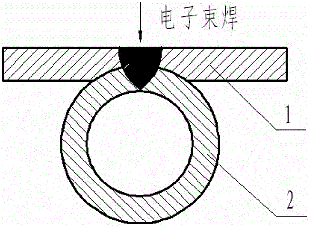
[0017] see figure 1 . The feed assembly consists of a feed sheet 1 and a bushing 2 below it. Electron beams can be used to penetrate and weld the upper feeder sheet and the lower casing into one body. The welding material is hard aluminum alloy, and the welding thickness is 1+1mm.

[0018] First, insert the acid-washed bushing into the equal-diameter groove of the fixture, install the feeder piece on the bushing, and use the rigid fixing method to use the pressure plate on the fixture to be "symmetrical at eight points on the left and right, and pressed up and down to fix it", so that the bushing Fit and press the feed piece, the pre-tightening force in the up and down direction is adjusted by the spring washer on the screw, a copper rod of equal diameter is inserted into the casing, and the two...


PUM

PropertyMeasurementUnit
thicknessaaaaaaaaaa
surface smoothnessaaaaaaaaaa

Abstract

The invention discloses a non-penetrating welding method of feed components through electron beams. According to the non-penetrating welding method, the needed technological process is simple, efficiency is high, deformation is little, welding seams are regular, welding precision is high, and the product percent of pass can be 100%. The non-penetrating welding method is realized through the technical scheme that in the welding process, scanning waveforms of the electron beams are set to be oval, the scanning amplitude in the X direction is set to be 2 mm to 3 mm, the scanning amplitude in the Y direction is set to be 4 mm to 6 mm, the scanning frequency is set to be 80 Hz to 100 Hz, the acceleration voltage is set to be 50 kV to 60 kV, the beam current is set to be 10 mA to 15 mA, the focus current is set to be 800 mA to 900 mA, any one set of specific values of is selected from the process parameters, the beam slope is set to be in an isosceles trapezoid shape, ascending time and descending time of the electron beams are both set to be 3s to 5s, and the welding seams are welded in a deflection scanning mode; the electron beams penetrate through feed pieces on a sleeve pipe to weld the feed pieces and the sleeve pipe under the feed pieces together. The non-penetrating welding method solves the problems that a conventional welding process is complex, thermal deformation is serious, and burning through and open solder are likely to happen.

Description

technical field [0001] The invention relates to an electron beam non-penetrating welding method for a power feed assembly, in particular to the electron beam non-penetrating welding which is suitable for parts structure design requirements. Background technique [0002] The feed assembly is a typical product on the fuel measurement and control system, and its manufacturing accuracy directly affects the important characteristics of the fuel measurement and control system. Therefore, there are strict requirements on the welding of feed components. Generally, there are two main processing methods for welding feed components: brazing and fusion welding. As the last process, there is no residual processing after welding, so the requirements for welding deformation control are strict, and the weld seam is not allowed to penetrate the casing, otherwise the feeder cannot pass through. Using the conventional welding method—brazing, the output heat is too large, the heat-affected zo...

Claims


Application Information

Patent Timeline
Patent Type & Authority Patents(China)
IPC IPC(8): B23K15/00B23K15/02
CPCB23K15/0053
Inventor 傅志勇
Owner 四川泛华航空仪表电器有限公司
Why Eureka
Try Eureka