

Impeller positioning structure
A positioning structure and impeller technology, applied to parts of pumping devices for elastic fluids, non-variable pumps, machines/engines, etc., can solve problems such as complex processing, and achieve less damage, save processing time, and quantity little effect
- Summary
- Abstract
- Description
- Claims
- Application Information
AI Technical Summary
Problems solved by technology
Method used
Image

Examples
Embodiment Construction
[0018] The present invention will be described in detail below in conjunction with the accompanying drawings and embodiments.
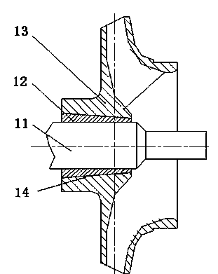
[0019] See figure 2 , shown in the figure is an impeller positioning structure, which is mainly composed of a pump shaft 11, a positioning sleeve 12 and an impeller 13.
[0020] The pump shaft 11 is connected with the motor to provide the impeller 13 with rotation power. At the position where the impeller needs to be set, a shaft section is machined.
[0021] The positioning sleeve 12, a tapered sleeve, is sleeved on the shaft section of the pump shaft and has an interference fit. In order to increase the versatility and fixing reliability of the positioning shaft sleeve 12, a 2-4mm wide slit is machined on it along the axial direction, so that there is a certain free adjustment space during the sleeve setting process.
[0022] The impeller 13 is composed of a hub and vanes. The inner surface of the hub is processed into a mating surface correspon...
PUM
 Abstract
Description
Claims
Application Information