

Rough machining method of integrated three-dimensional flow blade wheel
A ternary flow and integral technology, which is applied in metal processing equipment, manufacturing tools, milling machine equipment details, etc., can solve the problems of low processing efficiency, inability to solve arc chamfering and clearing corners well, and avoid over-cutting , shorten processing time, reduce wear effect
- Summary
- Abstract
- Description
- Claims
- Application Information
AI Technical Summary
Problems solved by technology
Method used
Image

Examples
Embodiment
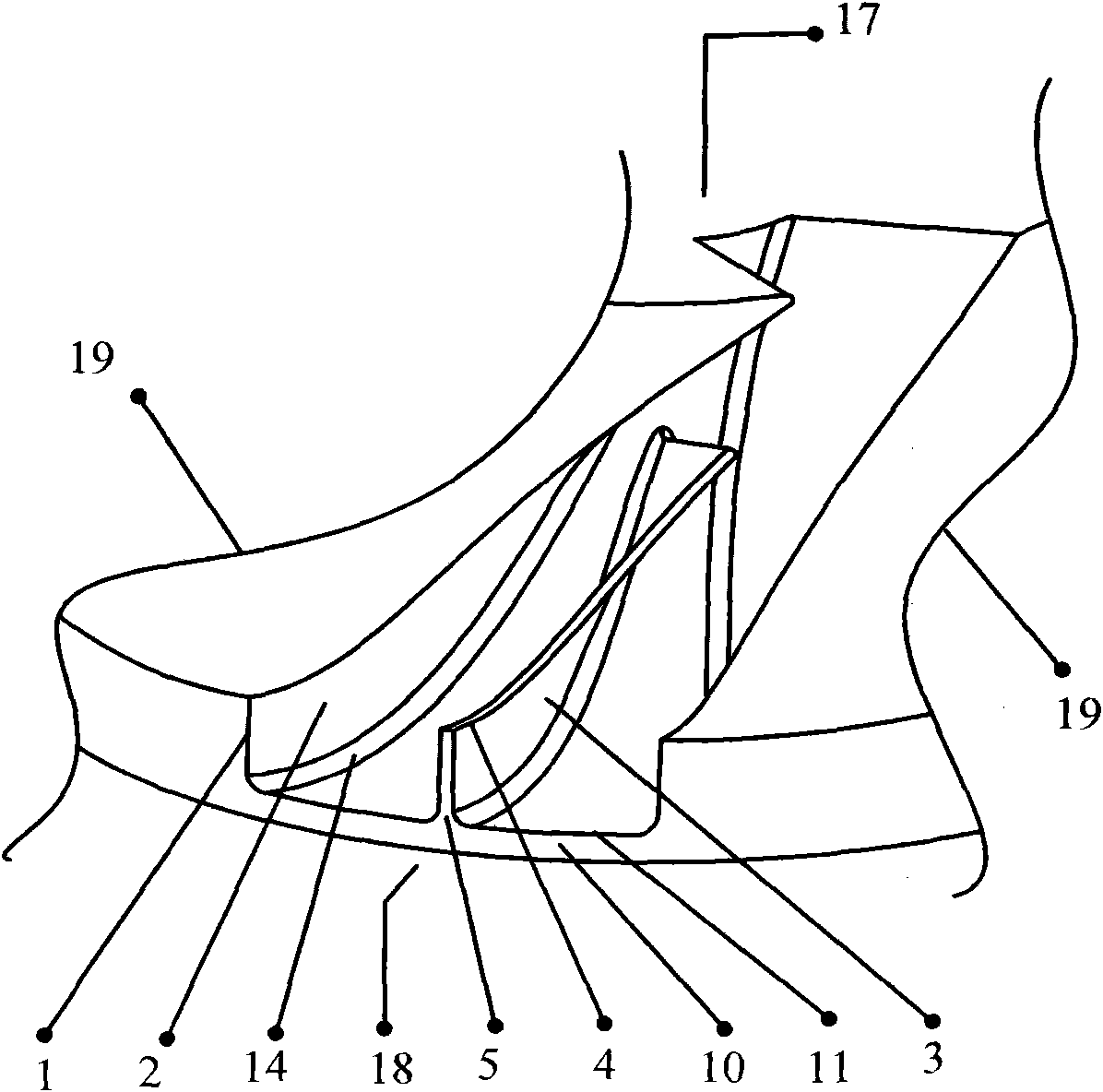
[0029] First select or make stainless steel integral ternary impeller blanks. Several spherical milling cutters of different specifications are used to mill and remove the material in the flow channel between every two blades. The milling starts from the blade wheel cover side 4 and gradually advances to the blade hub side 5 . as attached figure 2 As shown, the following process steps are included:
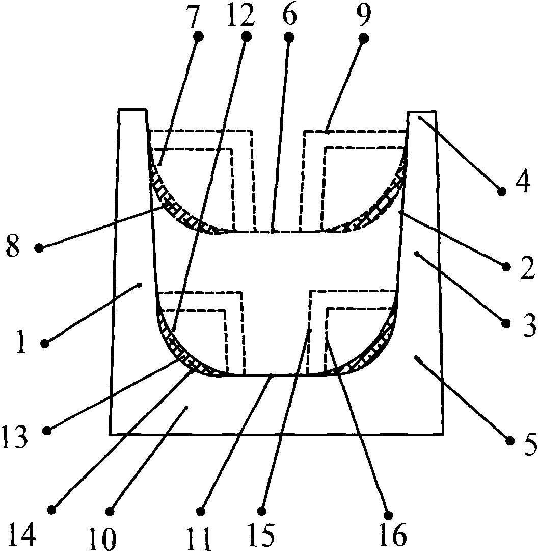
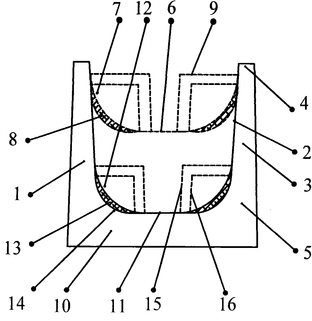
[0030] 1) Determine the number of milling layers and the milling depth of each layer according to the change of the flow channel space. As the milling depth changes from shallow to deep, the flow channel space changes from large to small, and the specifications of the spherical milling cutter used gradually change from large to small ;
[0031] 2) A certain layer adopts the largest specification spherical milling cutter allowed to be used in the flow channel space for milling processing, and the ball head radius Ra9 of the milling cutter of a certain layer is set, and after m...
PUM
 Abstract
Description
Claims
Application Information