Magnetic path horizontal rotary type hoisting permanent magnet

A horizontally rotating permanent magnet technology, applied in the field of lifting permanent magnets, can solve the problems of high processing roughness, inability to process, and inability to lock the ratchet wheel, and achieve the effect of saving processing time and reducing processing difficulty

Active Publication Date: 2015-01-28
雷艳
View PDF7 Cites 10 Cited by
  • Summary
  • Abstract
  • Description
  • Claims
  • Application Information

AI Technical Summary

Problems solved by technology

[0003] 1. Since the ratchet cannot be locked, when the suction capacity reaches the limit, the magnetic force will push the ratchet to rotate and unload automatically, which poses a very large installation hazard;
[0004] 2. It is easy to appear that the left and right ratchets and pawls are not synchronized, and the phenomenon of left rotation and right non-rotation occurs, which affects the performanc

Method used


Image

  • Magnetic path horizontal rotary type hoisting permanent magnet
  • Magnetic path horizontal rotary type hoisting permanent magnet
  • Magnetic path horizontal rotary type hoisting permanent magnet

Examples


example 1

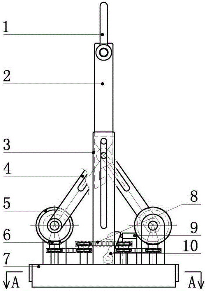
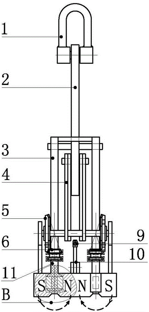
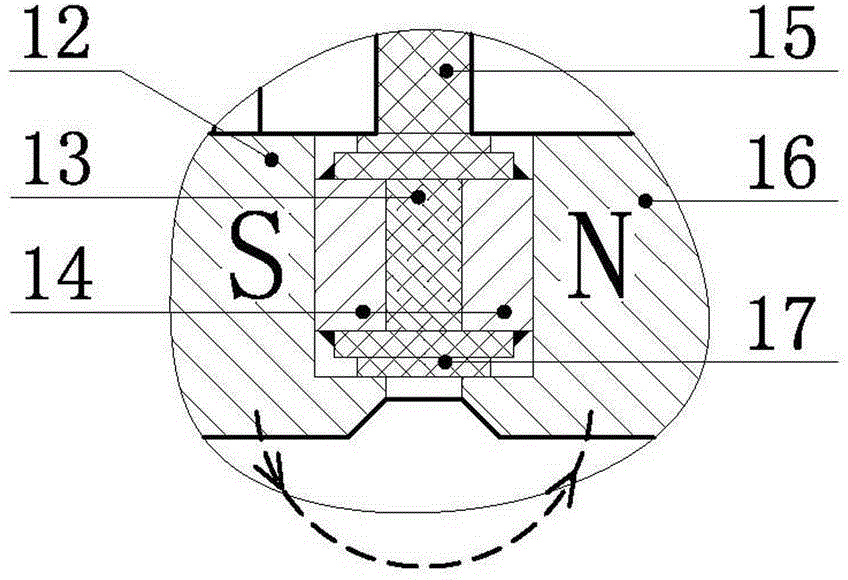
[0028] Iron-absorbing state: the lifting ring (1) and the hooked boom (2) drop to the bottom, forcing the hook (10) to unhook and the self-elastic device (9) retracts and locks, and the lifting ring (1) and the hooked boom (2) Lifting up, it drives the left and right hoists (4) and the large bevel gear (5) to rotate, and is transmitted to the small bevel gear (6) to rotate horizontally, and then is transmitted to the multiple gears in the magnetic system body (7) through the roller chain (8). A rotating magnetic shaft (11) rotates (see figure 1 and figure 2 ), when the S pole surface and the N pole surface of the permanent magnet block (13) in each rotating magnetic shaft (11) are on the same surface, a magnetic field is generated at the bottom of the lifting permanent magnet to reach the iron-absorbing state (see Figure 5 ).

[0029] Iron unloading state: the lifting ring (1) and the hooked boom (2) are lowered again, driving the left and right hanging plates (4) and the ...

example 2

[0031] As an improvement, in order to enhance the magnetic field, a group of fixed permanent magnets ( 20) (see Figure 7 ), when the permanent magnet block (13) in each rotating magnetic shaft (11) rotates to the same side as the S pole surface and N pole surface of the side fixed permanent magnet (20), the bottom of the lifting permanent magnet generates magnetism, reaching iron-absorbing state (see figure 2 ); when the permanent magnet block (13) in each rotating magnetic axis (11) rotates 180 degrees, it is not on the same side as the S pole surface and the N pole surface of the side fixed permanent magnet (20), and the S pole surface of the two sets of permanent magnets The pole and the N pole conduct each other, the magnetic circuit cancels each other, the bottom of the lifting permanent magnet does not show magnetism, and the iron unloading state is reached (see Figure 8 ).

example 3

[0033] As an improvement, the rotating magnetic shaft (11) of the main body of the magnetic system in Example 1 and Example 2 rotates, and the rotating magnetic shaft (11) is driven by a motor, hydraulic transmission, pneumatic transmission or other mechanical means.


PUM


Abstract

The invention provides a magnetic path horizontal rotary type hoisting permanent magnet. The magnetic path horizontal rotary type hoisting permanent magnet is mainly composed of three parts, namely a mechanical rotation part, a magnetic system body and a control device, and is characterized in that a lifting ring of the mechanical rotation part is arranged on a lifting rod with a hook; when the lifting rod with the hook slides in a lifting rod slide rail, left and right lifting bars and large bevel gears are driven to rotate, then small bevel gears are driven to horizontally rotate, and finally, a plurality of rotary magnetic shafts in the magnetic system body are driven to rotate by a roller chain so as to change a magnetic path; and each lifting or descending of the lifting rod with the hook is used for controlling the unhooking or the hooking of the hook, so that the rotary angles of the magnetic shafts in the magnetic system body are controlled to control the circulation of two states, namely iron suction and iron releasing, of the hoisting permanent magnet; and a ratchet wheel is not used so that the problems of an old type hoisting permanent magnet that the iron suction is not synchronous, the machining is difficult and the like are completely overcome.

Description

technical field [0001] The invention relates to the technical field of lifting permanent magnets, in particular to a magnetic circuit horizontally rotating lifting permanent magnet. Background technique [0002] At present, the self-unloading lifting permanent magnet on the market (patent number: 200420035640.8, patent number: 200420035639.5) is lifted up and down by the left and right two sets of hoists on the magnetic body, respectively driving the corresponding pawl and ratchet group to rotate, and driving the side magnetic pole chain The wheel rotates, and then drives the fixed-angle circular rotation of the side magnetic poles, so that the magnetic circuits can cancel each other or superimpose each other to realize the sequential cycle of suction and discharge. Its main disadvantages: [0003] 1. Since the ratchet cannot be locked, when the suction capacity reaches the limit, the magnetic force will push the ratchet to rotate and unload automatically, which poses a ver...

Claims


Application Information

Patent Timeline
IPC IPC(8): B66C1/04
CPCB66C1/04
Inventor 雷艳
Owner 雷艳
Why Eureka
Try Eureka