
Matrix and countermatrix type bending machine for right-hand and left-hand bending an elongated piece

一种细长工件、弯曲机的技术,应用在弯曲机领域

Active Publication Date: 2015-01-21
CML INTERNAT SPA
View PDF13 Cites 10 Cited by
  • Summary
  • Abstract
  • Description
  • Claims
  • Application Information

AI Technical Summary

Problems solved by technology

Although die-plus-counter-die type bending machines equipped with a pair of pipe holders on the die already exist, they are only used to bend pipes of different diameters

Method used


Image

  • Matrix and countermatrix type bending machine for right-hand and left-hand bending an elongated piece
  • Matrix and countermatrix type bending machine for right-hand and left-hand bending an elongated piece
  • Matrix and countermatrix type bending machine for right-hand and left-hand bending an elongated piece

Examples


Embodiment Construction

[0027] Objects and advantages of the present invention will become more apparent from the accompanying drawings and the following description. Variations and modifications of the embodiments shown and described may be substituted, as will be apparent to those skilled in the art, without departing from the principles of the invention.

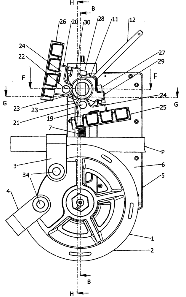
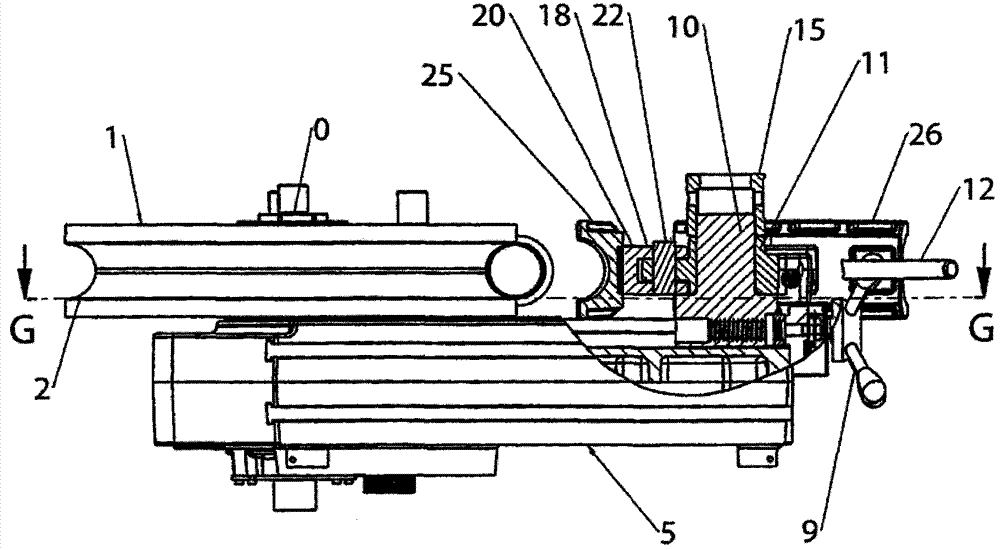
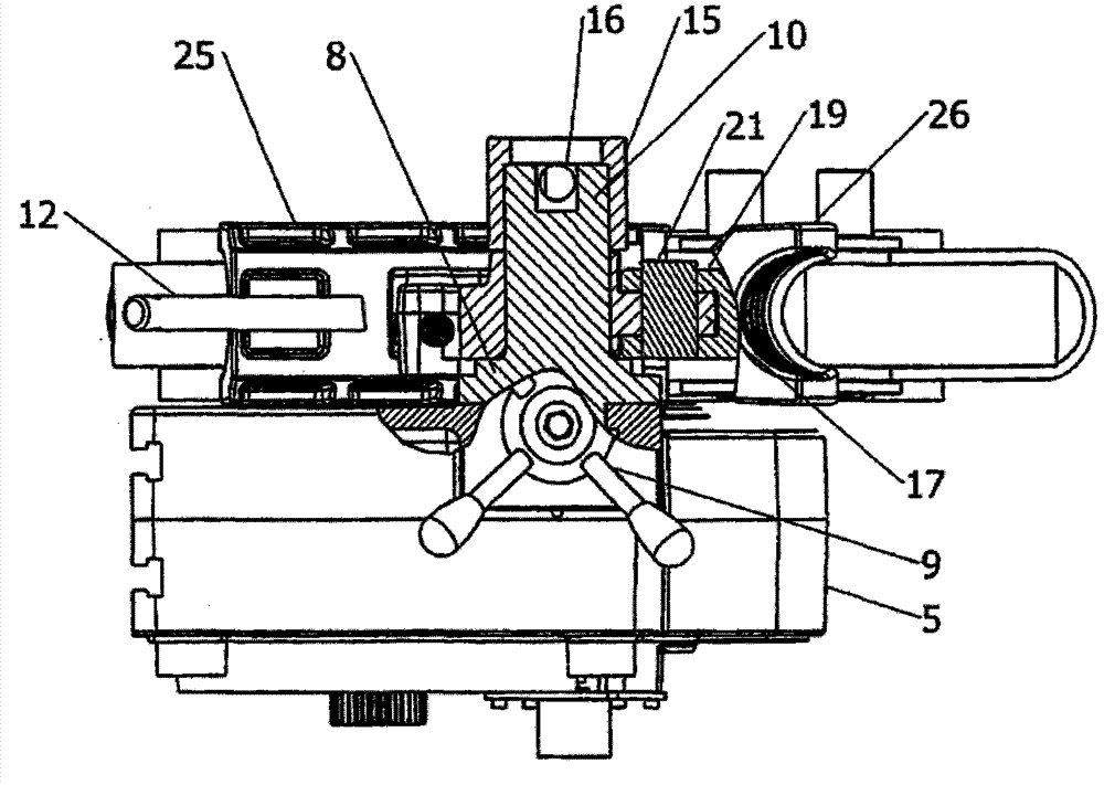
[0028] First, refer to figure 1 , which shows a top view of the bending machine according to the invention at the initial stage in the bending operation. As mentioned above, bending machines are of the die plus opposing die type. It includes the figure 2 A roll-shaped die (1) of a partially circumferential groove (2) best shown in the figure 2 is along the figure 1 The top view is a side view partially cut away on line B-B. The part-circumferential groove (2) is interrupted at its two ends, where the respective retaining means (3, 4) are provided. As is known, such holding means (3, 4) have an approximately U-shape, the sides of which ar...


PUM


Abstract

A matrix and countermatrix type bending machine for right- and left-hand bending an elongated piece (P) comprises a roller-shaped matrix (1) provided with a partial circumferential groove (2) that is interrupted at its two ends, the matrix (1) being driven by the shaft (0) of a motor, and a pair of countermatrices (25, 26) being carried by respective countermatrix support members (19, 20) pivoted on a turret (11) that is rotatable mounted on a slide (8) in a given arc of rotation about its axis perpendicular to the slide (8) by a lever (12). The matrix (1) has an elongated piece retaining means (3, 4). The first or the second countermatrix (25, 26) are selectable to co-operate with the matrix (1) in bending said elongated piece (P) depending on the required curvature to right hand or left hand.

Description

technical field [0001] The present invention relates to a die plus opposing die type bending machine for bending slender workpieces to the right and left. Background technique [0002] Bending machines capable of bending slender workpieces such as pipes to the right and left already exist on the market. Among these, one may cite the bending machine provided by BLM S.p.A., Cantù, Italy, holder of US Patent 6,434,993. Said patent discloses a bending machine having a bed comprising a body and a head portion, a pair of longitudinal guides on the body portion, a pair of transverse guides on the head portion, for holding the workpiece and being Body slide mounted on longitudinal guides, head slide mounted on lateral guides, workpiece bending assembly mounted on head slide and comprising an elongated shaft, at opposite end regions of said shaft A pair of bending dies, a pair of bending arms each operable for bending a workpiece against the respective bending dies, and a drive for...

Claims


Application Information

Patent Timeline
Patent Type & Authority Applications(China)
IPC IPC(8): B21D7/024
CPCB21D7/04B21D7/024
Inventor A·卡波鲁索
Owner CML INTERNAT SPA
Learn More