Automatic optical detection mechanism of liquid crystal module

An automatic optical detection and liquid crystal module technology, applied in optics, nonlinear optics, instruments, etc., can solve problems such as low work efficiency, difficult connection operation, damage to liquid crystal modules, etc., and achieve low probability of missed detection or false detection , to avoid the difficulty of connection operation and to speed up the detection speed

Active Publication Date: 2015-03-25
SUZHOU JINGLAI OPTO CO LTD
View PDF8 Cites 7 Cited by
  • Summary
  • Abstract
  • Description
  • Claims
  • Application Information

AI Technical Summary

Problems solved by technology

The problems in this method are: 1. The error of the result of manual naked eye detection is too large, which is prone to missed detection and false detection; 2. It is difficult to manually move the liquid crystal module and the connection operation of the signal generating device, and it is easy to damage the liquid crystal module. 3. Manual detection is prone to fatigue, time-consuming and laborious, low work efficiency and high cost

Method used


Image

  • Automatic optical detection mechanism of liquid crystal module
  • Automatic optical detection mechanism of liquid crystal module
  • Automatic optical detection mechanism of liquid crystal module

Examples


Embodiment Construction

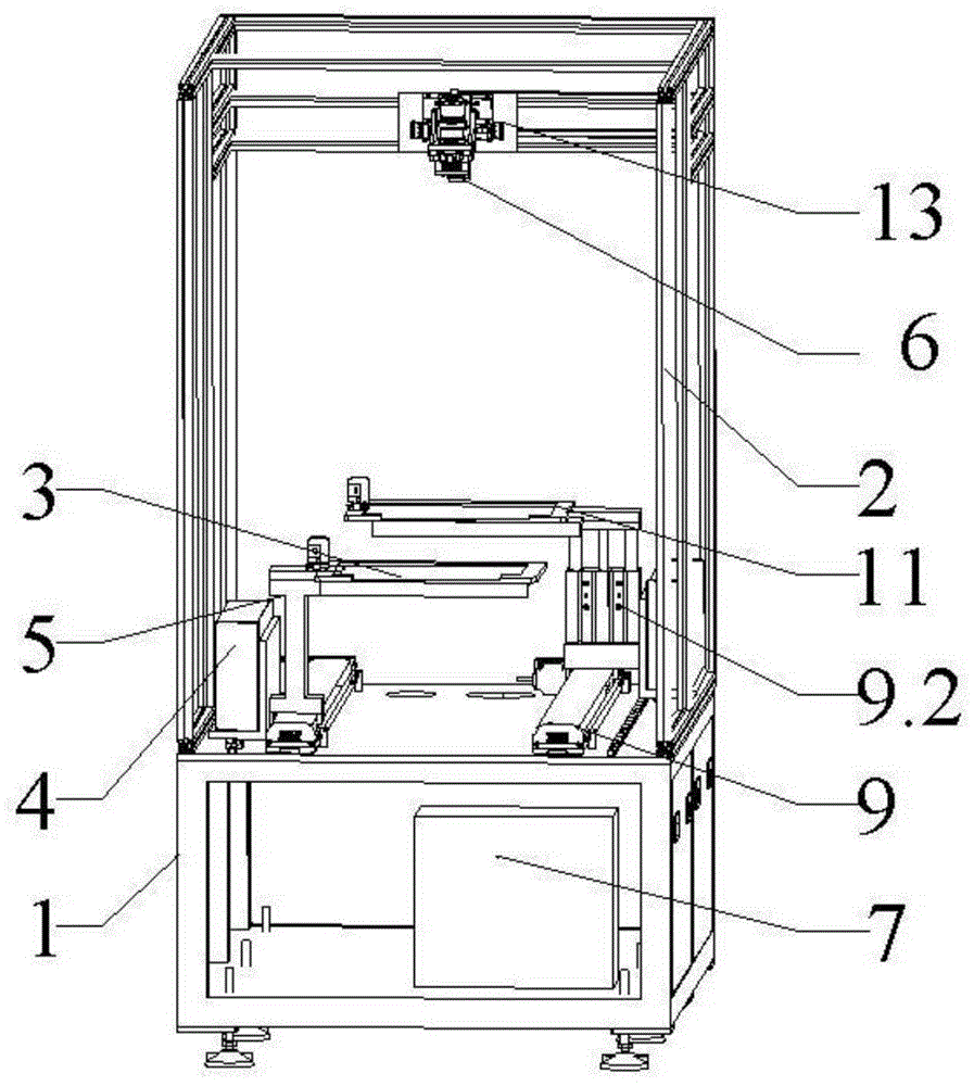
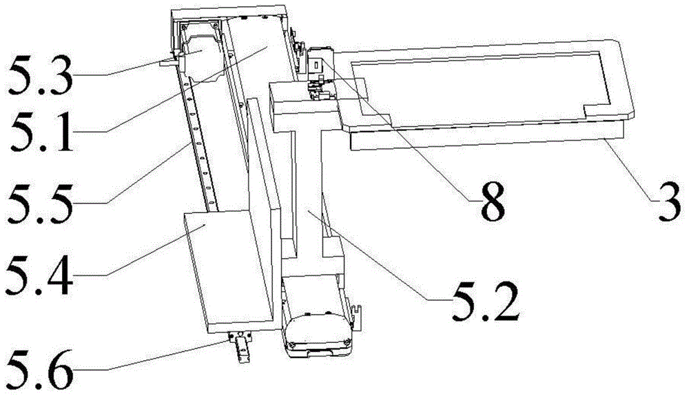
[0031] Such as Figure 1~5 As shown, an automatic optical inspection mechanism for a liquid crystal module includes a carrying platform 1 and a bracket 2 fixed on the upper end of the carrying platform 1. A control unit 7 is arranged inside the carrying platform 1, and a first carrying mechanism is arranged on the upper end surface of the carrying platform 1. Tool 3, the first carrying tool 3 is mainly used to carry the liquid crystal module to ensure that the liquid crystal module can be stably at the position to be detected. The first carrying fixture 3 is generally made according to the shape and size of the liquid crystal module, and a special fixture can also be used to fix the liquid crystal module on the first carrying fixture 3 .

[0032] The carrying platform 1 is also installed with a first graphic signal generating device 4 that sends image signals to the liquid crystal module placed on the first carrying fixture 3, and the first graphic signal generating device 4 s...


PUM


Abstract

The invention relates to the field of assembly detection of liquid crystal modules, in particular to an automatic optical detection mechanism of a liquid crystal module. The automatic optical detection mechanism comprises a first bearing jig used for bearing the liquid crystal module, a first graph signal generating device used for sending image signals to the liquid crystal module placed on the first bearing jig, a first driving device used for driving the first bearing jig and the first graph signal generating device to move along a first guiding device arranged on a bearing platform, a CCD image sensor used for capturing image information of a liquid crystal module screen used for receiving the image signals, and a control unit used for processing the image information captured by the CCD image sensor to judge whether the liquid crystal module is qualified. The automatic optical detection mechanism achieves automatic operation of liquid crystal module detection, greatly improves efficiency of liquid crystal module detection, saves a lot of manpower and material resources, shortens working time and has great promotion value.

Description

technical field [0001] The invention relates to the field of liquid crystal module assembly and detection, in particular to an automatic optical detection mechanism of a liquid crystal module. Background technique [0002] In view of the rapid development of LCD monitors and LCD TVs in recent years, consumers have put forward higher requirements for the display quality of LCD module screens. In the prior art, multi-step manual detection is used for screen detection. This manual detection method is By sending an image signal to the liquid crystal module to be tested to perform point screen, after the liquid crystal module to be tested receives the signal, observe the display of the liquid crystal module with the naked eye to judge whether the liquid crystal module is assembled properly. The problems in this method are: 1. The error of the result of manual naked eye detection is too large, which is prone to missed detection and false detection; 2. It is difficult to manually m...

Claims


Application Information

Patent Timeline
Patent Type & Authority Applications(China)
IPC IPC(8): G02F1/13
CPCG02F1/1303G02F1/1309
Inventor 吴计武李光赵赟彬
Owner SUZHOU JINGLAI OPTO CO LTD
Why Eureka
Try Eureka