Space truss formwork supporting system and construction method thereof

A space truss and construction method technology, applied in artificial islands, water conservancy projects, infrastructure projects, etc., can solve problems such as the inability of vertical poles to stand on the ground, easily cause accidents, and fail to meet construction requirements, and achieve fast and safe construction, bearing capacity. Large, adaptable effects

Active Publication Date: 2015-04-01
GUANGZHOU HENGSHENG CONSTR ENG
View PDF8 Cites 9 Cited by
  • Summary
  • Abstract
  • Description
  • Claims
  • Application Information

AI Technical Summary

Problems solved by technology

During the engineering construction, the cast-in-place formwork system of the cast-in-place concrete platform cannot meet the construction requirements due to the limitations of wading, conventional construction technology and nearby terrain.
Generally speaking, the truss composition requires vertical poles as support points, but for the increasing domestic water platform, hydrophilic platform and other cast-in-place concrete formwork projects limited by terrain, if the conventional truss formwork system is used, it will be affected by water depth, Affected by problems such as water flow and terrain restrictions, a series of technical problems such as the inability of the pole to stand on the ground appeared
Therefore, in the case of limited terrain conditions, especially for wading projects, since the full hall frame must enter the water, it is easy to cause accidents due to the erosion of water flow and the impact of debris on the water. Steel bar and concrete construction is a difficult point in the prior art

Method used


Image

  • Space truss formwork supporting system and construction method thereof
  • Space truss formwork supporting system and construction method thereof
  • Space truss formwork supporting system and construction method thereof

Examples


Embodiment Construction

[0032] The following will clearly and completely describe the technical solutions in the embodiments of the present invention with reference to the accompanying drawings in the embodiments of the present invention. Obviously, the described embodiments are only some, not all, embodiments of the present invention. Based on the embodiments of the present invention, all other embodiments obtained by persons of ordinary skill in the art without creative efforts fall within the protection scope of the present invention.

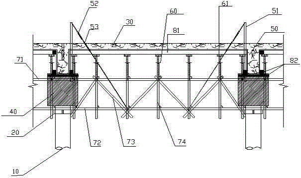
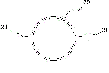
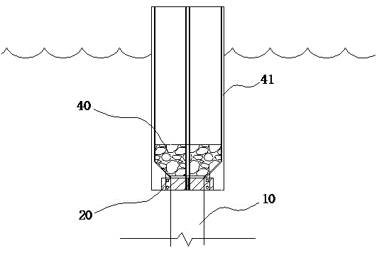
[0033] Such as Figure 1 to Figure 3 As shown, it is a structural schematic diagram of a space truss formwork system in a preferred embodiment of the present invention. The space truss formwork system of the present invention includes a prefabricated pipe pile 10 arranged in water, and a steel hoop fixed on the prefabricated pipe pile 10 20. The cap 40 poured on the top of each prefabricated pipe pile 10, the frame beam 50 poured above the cap 40, and the platform ...


PUM


Abstract

The invention discloses a space truss formwork supporting system and a construction method thereof; the space truss formwork supporting system comprises a precast tubular pile arranged in the water, a steel hoop fixed on the precast tubular pile, a concrete bearing table formed at the top of each pile by casting and a steel tube stand column, a diagonal draw bar used for connecting the stand column and a truss chord member node, a space truss composed of the steel tube and fastener embedded in the bearing table; a jacking is mounted on the stand column of the space truss, the wood brace is arranged on the jacking, a template is mounted on the wood brace for binding the reinforcing steel bar and casting the concrete beam slab. The space truss formwork supporting system takes the precast tubular pile as the fulcrum in the limit situation of the topographic condition, the non-floor type space truss formwork supporting system is used for the construction of the beam and slab reinforcing steel bar and concrete, the conventional vertical support system is changed into the space horizontal support system; the computer analog technology is adopted and the space truss is made of the steel tube and used as the bearing support system of the cast-in-place beam and slab, the structure safe construction is guaranteed and the construction is quick and safe.

Description

technical field [0001] The invention relates to the technical field of building construction, in particular to a space truss formwork support system and a construction method thereof. Background technique [0002] Truss is a structure composed of rods connected by hinges at both ends. The truss is composed of straight rods and generally has a plane or space structure with triangular units. The truss rods mainly bear axial tension or pressure, so that they can make full use of The strength of the material, when the span is large, can save material, reduce self-weight and increase rigidity compared with solid web beams. The advantage of the truss is that the rods mainly bear tension or pressure, which can give full play to the role of materials, save materials, and reduce structural weight. Commonly used are steel truss, reinforced concrete truss, prestressed concrete truss, wooden truss, steel and wood composite truss, steel and concrete composite truss. [0003] With the r...

Claims


Application Information

Patent Timeline
Patent Type & Authority Applications(China)
IPC IPC(8): E02B17/00
CPCE02B17/00E02B17/0008E02B17/025E02B2017/0056
Inventor 赵自亮杨泽民李传辉罗宏张连录夏立明李慧莹
Owner GUANGZHOU HENGSHENG CONSTR ENG
Why Eureka
Try Eureka