Integrated engine brake rocker arm structure

An integrated, braking mechanism technology, used in engine components, machines/engines, mechanical equipment, etc., can solve problems such as high manufacturing and assembly costs, asymmetric load on valve bridges, and inability to work properly, and shorten the oil circuit stroke. , Easy installation and adjustment, the effect of improving sensitivity and reliability

Active Publication Date: 2015-04-08
ZHEJIANG KANGHE MECHANICAL ENG CO LTD
View PDF8 Cites 34 Cited by
  • Summary
  • Abstract
  • Description
  • Claims
  • Application Information

AI Technical Summary

Problems solved by technology

[0008] However, there are still many deficiencies in the development and research of this integrated rocker system.
For example, the No. 6234143 patent of the U.S. Mark (Mack) truck company in 2001 disclosed another integrated rocker brake, which added an exhaust gas recirculation (EGR) boss to the original cam mechanism, and increased the valve bridge. However, only one exhaust valve is opened during braking, and there is also an asymmetric load on the valve bridge and the rocker arm; in 2001, Cummins (Cummins) Engine Company disclosed a valve with a valve lift reset mechanism in US Patent No. 6253730 The integrated rocker brake system solves the asymmetric load problem caused by opening the single valve when braking.
However, the reset time is too short and the reset height is too small, so it cannot work normally at high engine speeds; the published application number of Chery Automobile Co., Ltd. is an engine brake device of 200810024409.2, which is easy to control, but needs to add an additional cam Switching device, relatively expensive to manufacture and assemble

Method used


Image

  • Integrated engine brake rocker arm structure
  • Integrated engine brake rocker arm structure
  • Integrated engine brake rocker arm structure

Examples


Embodiment 1

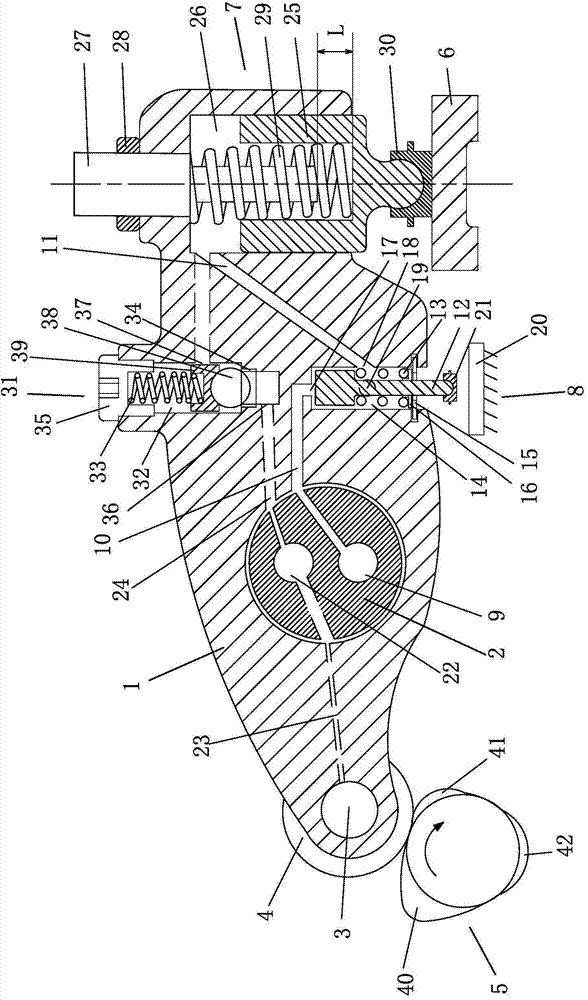
[0034] Embodiment 1: see figure 1 :

[0035]An integrated engine brake rocker structure, the rocker arm 1 is set on the rocker shaft 2, one end of the rocker arm 1 is provided with a roller 4 through a pin 3, the pin 3 is a copper pin, and the roller 4 is in contact with the exhaust cam 5 Connected, the other end of the rocker arm 1 is provided with a brake mechanism 7 for operating the exhaust valve bridge 6, and the exhaust valve bridge 6 is provided under the brake mechanism 7, and the brake mechanism 7 controls the action of the exhaust valve bridge 6. An oil control valve mechanism 8 is installed on the rocker arm 1 between the brake mechanism 7 and the rocker arm shaft 2, a brake oil passage 9 and a lubricating oil passage 22 are arranged on the rocker arm shaft 2, and a communication oil control valve mechanism is provided on the rocker arm 1. The first brake oil passage 10 of the valve mechanism 8, and the second brake oil passage 11 connecting the oil control valve m...

Embodiment 2

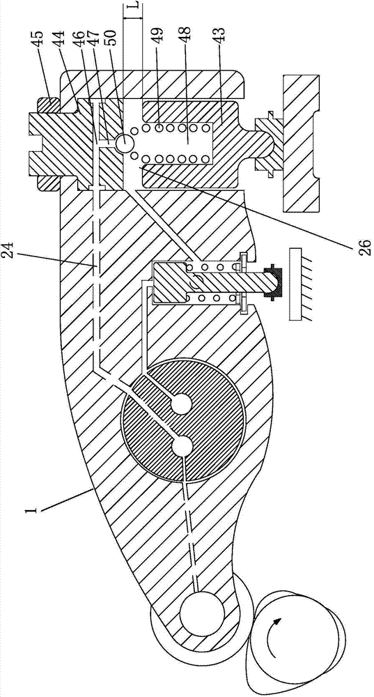
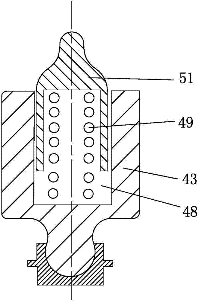
[0051] Example 2: see figure 2 , 3 :

[0052] The structure of this embodiment is basically the same as that of Embodiment 1, the difference being that the braking mechanism 7 of this embodiment has a self-contained check valve structure.

[0053] The brake mechanism 7 is as follows: the brake piston 43 is arranged in the brake chamber 26 on the rocker arm 1 close to the exhaust valve end, the upper end of the brake chamber 26 is provided with an adjustment bolt 44, and the adjustment bolt 44 passes through the lock nut 45 fixed, the adjusting bolt 44 is provided with a radial oil hole 46 and an axial oil hole 47, the radial oil hole 46 communicates with the second lubricating oil passage 24, and the axial oil hole 47 communicates with the blind hole 48 on the brake piston 43, A spring 49 is arranged in the blind hole 48, and the upper end of the spring 49 is provided with a steel ball 50 or a valve core 51 with a ball head. The compensation gap L between the upper end of ...

Embodiment 3

[0055] Embodiment 3: See Figure: 4-6:

[0056] The structure of this embodiment is basically the same as that of Embodiment 1, the difference being that the structure of the oil control valve mechanism is different:

[0057]The oil control valve mechanism 8 is: the oil control valve plunger 52 is installed in the lower piston chamber of the rocker arm 1, and the oil control valve plunger 52 is respectively provided with annular grooves 53, 54 and an axially arranged straight groove 55 for connecting the two annular grooves 53, 54; one end of the spring piece 56 is fixed on one side of the rocker arm 1 by a bolt 57, and the other end is clamped on the lower part of the oil control valve plunger 52 On the annular groove 54, two guide bolts 58, 59 are screwed on the rocker arm 1, and the inner ends of the two guide bolts 58, 59 are arranged in the straight groove 55 of the oil control valve plunger 52. Under normal conditions, the oil control valve plunger 52 is in the upper non...


PUM


Abstract

The invention belongs to the technical field of engines, and particularly relates to an integrated engine brake rocker arm structure. A rocker arm is arranged on a rocker arm shaft, a roller is arranged at one end of the rocker arm and connected with a venting cam in a contacting manner, a brake mechanism with a one-way valve structure is arranged at the other end of the rocker arm and operates a venting gate bridge, an oil control valve mechanism is mounted on the rocker arm between the brake mechanism and the rocker arm shaft, a brake oil channel and a lubricating oil channel are formed in the rocker arm shaft, a first brake oil channel communicated with the oil control valve mechanism and a second brake oil channel communicated with the oil control valve mechanism and the brake mechanism are formed in the rocker arm, the first brake oil channel is connected or disconnected with the second brake oil channel through the oil control valve mechanism, rotation of the venting cam drives the rocker arm to swing around the rocker arm shaft, and the venting cam is matched with a solenoid valve signal to drive the oil control valve mechanism and the brake mechanism to act, so that the action of the venting gate bridge is controlled. The brake mechanism of an engine is integrally modular, simple, low in cost, convenient to mount and adjust and wide in applicability.

Description

Technical field: [0001] The invention belongs to the technical field of engines, in particular to an integrated engine braking rocker arm structure. Background technique: [0002] With the continuous development of the domestic economic situation and the rapid construction of expressways, the logistics and transportation industry with automobiles as the main means of transportation has become an important part of the national economy. Driven by science and technology, trucks are increasingly becoming heavy-duty and high-speed. Traditional mechanical friction brakes are overwhelmed at work and often fail due to severe friction wear and high temperature of the brake hub, resulting in frequent traffic accidents. hair, endangering personal safety. In this case, high-efficiency, sustained and stable retarding performance and engine brakes without material consumption have received widespread attention and have been gradually promoted and applied. At the end of 2012, the relevan...

Claims


Application Information

Patent Timeline
Patent Type & Authority Applications(China)
IPC IPC(8): F01L13/06F01L1/18
CPCF01L1/18F01L13/06F01L13/065
Inventor 马国伟关大众陈能舜
Owner ZHEJIANG KANGHE MECHANICAL ENG CO LTD
Why Eureka
Try Eureka