Integrated rocker arm used for achieving engine braking

An engine braking, integrated technology, applied in the field of integrated rocker arms, can solve the problems of high manufacturing and assembly costs, increase system complexity, etc., to shorten the oil circuit stroke, improve sensitivity and reliability, and improve fatigue life. Effect

Active Publication Date: 2015-10-14
ZHEJIANG KANGHE MECHANICAL ENG CO LTD
View PDF7 Cites 16 Cited by
  • Summary
  • Abstract
  • Description
  • Claims
  • Application Information

AI Technical Summary

Problems solved by technology

[0008] However, there are still many deficiencies in the development and research of this integrated rocker system.
For example, in 1974, JVS Company of the United States disclosed a method of hydraulically locking the brake piston in the extended position during braking, and transmitting the cam movement to the valve bridge to open two valves at the same time in patent No. 3809033. The rocker arm is subjected to a huge load; the integrated rocker brake system for the overhead four-valve engine disc

Method used


Image

  • Integrated rocker arm used for achieving engine braking
  • Integrated rocker arm used for achieving engine braking
  • Integrated rocker arm used for achieving engine braking

Examples


Embodiment 1

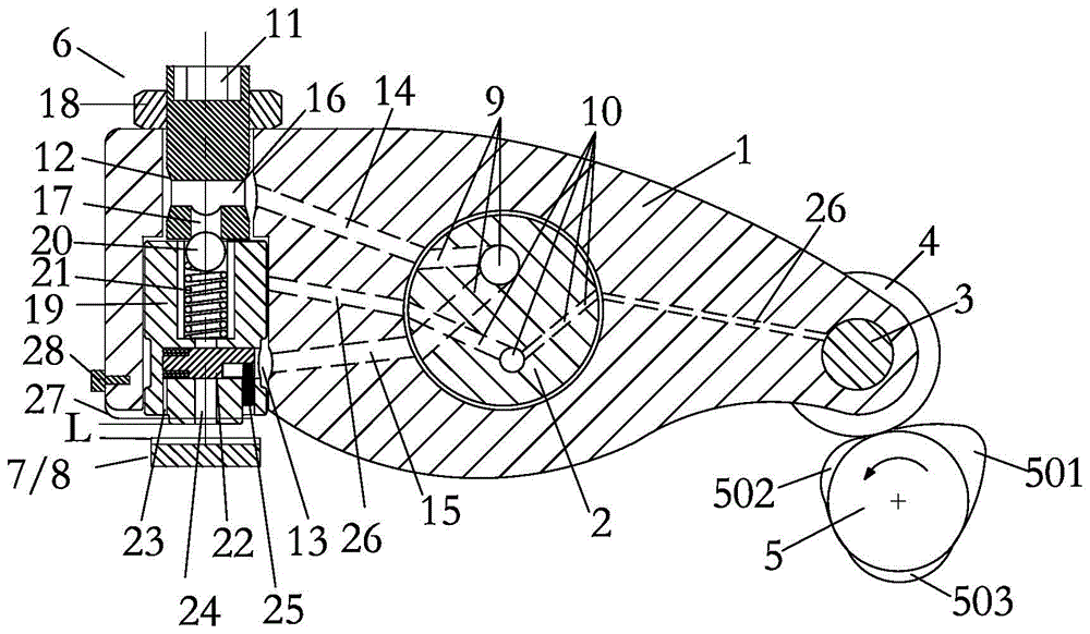
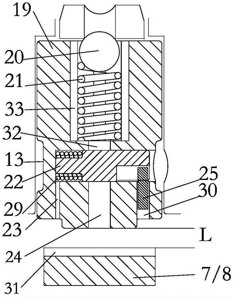
[0038] Embodiment 1: see figure 1 -2:

[0039] An integrated rocker arm for generating engine braking. The rocker arm 1 is arranged on the rocker arm shaft 2. One end of the rocker arm 1 is provided with a roller 4 through a pin 3. The roller 4 is in contact with the exhaust cam 5. The air cam 5 is provided with a normal exhaust protrusion 501, a compression release brake protrusion 502 and a brake recirculation protrusion 503, and a brake mechanism 6 is arranged at the other end of the rocker arm 1, and the brake mechanism 6 It includes a brake adjusting bolt 11 and a brake piston arranged at the lower part of the brake adjusting bolt 11, an exhaust valve bridge 7 or a single exhaust valve 8 is arranged under the brake piston, and a brake valve is arranged on the rocker shaft 2. The oil passage 9 and the lubricating oil passage 10 are provided with a first lubricating oil passage 26 connecting the pin 3 and the middle part of the brake piston 19 on the rocker arm 1 .

[004...

Embodiment 2

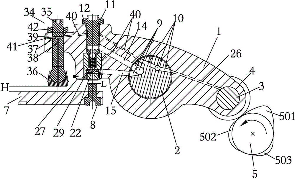
[0051] Example 2: see image 3 :

[0052] The structure of this embodiment and embodiment 1 is basically the same, and its difference is:

[0053] On the basis of the structure of Embodiment 1, an adjustment screw assembly 34 for operating the exhaust valve bridge exhaust is added on the rocker arm 1 outside the braking mechanism, and the braking mechanism 7 of this embodiment is used to open the single exhaust valve 8.

[0054] The adjusting screw assembly 34 includes an exhaust adjusting screw 35 and a socket 36 arranged below the exhaust adjusting screw 35. The adjusting screw 35 is fixed on the rocker arm 1 by a nut 42, and a diameter is provided on the upper end of the exhaust adjusting screw 35. To the oil passage 37, and from the radial oil passage 37 down and through the radial oil passage 37 of the socket 36, the radial oil passage 37 of the exhaust adjustment screw 35 is also provided with a third annular oil groove 39 , the rocker arm 1 is provided with a second ...

Embodiment 3

[0060] Embodiment 3: see Figure 4 :

[0061] The difference between this embodiment and Embodiment 2 lies in the difference in the structure of the adjusting screw assembly 34 .

[0062]The adjusting screw assembly 34 includes an exhaust adjusting screw 35 and a socket 36 arranged below the exhaust adjusting screw 35. The exhaust adjusting screw 35 is fixed on the rocker arm by a nut 42, and the upper end of the exhaust adjusting screw 35 A radial oil passage 37 is provided, and an axial oil passage 38 runs downwards from the radial oil passage 37 and passes through the socket 36, and the exhaust adjustment screw 35 is also provided with a third annular oil groove at the radial oil passage 37 39. A second lubricating oil passage 40 is provided on the rocker arm, and the second lubricating oil passage 40 communicates with the lubricating oil passage on the rocker shaft, and the outer end of the second lubricating oil passage 40 communicates with the outside world. 41 is bloc...


PUM


Abstract

The invention belongs to the technical field of engines and particularly relates to an integrated rocker arm used for achieving engine braking. The rocker arm is arranged on a rocker arm shaft. A driving mechanism driving the rocker arm to swing around the rocker arm shaft is arranged at one end of the rocker arm, and a braking mechanism is arranged at the other end of the rocker arm. The rocker arm shaft is provided with a braking oil channel and a lubricating oil channel. A braking adjusting bolt and a braking piston are communicated with the braking oil channel in the rocker arm shaft through a first braking oil channel and a second braking oil channel in the rocker arm. The braking piston is further communicated with the lubricating oil channel in the rocker arm shaft through a first lubricating oil channel in the rocker arm. The lubricating oil channel in the rocker arm shaft is further communicated with the driving mechanism through a second lubricating oil channel. The driving mechanism drives the rocker arm to swing around the rocker arm shaft and controls actions of the braking mechanism in cooperation with signals of an electromagnetic valve so as to control actions of an exhaust valve bridge or a single exhaust valve. The integrated rocker arm used for achieving engine braking does not need to be additionally provided with a complex mechanical hydraulic structure, and integration modularization, simplification and low cost of an engine braking mechanism are achieved.

Description

Technical field: [0001] The invention belongs to the technical field of engines, in particular to an integrated rocker arm for generating engine braking. Background technique: [0002] With the continuous development of the domestic economic situation and the rapid construction of expressways, the logistics and transportation industry with automobiles as the main means of transportation has become an important part of the national economy. Driven by science and technology, trucks are increasingly becoming heavy-duty and high-speed. Traditional mechanical friction brakes are overwhelmed at work and often fail due to severe friction wear and high temperature of the brake hub, resulting in frequent traffic accidents. hair, endangering personal safety. In this case, high-efficiency, sustained and stable retarding performance and engine brakes without material consumption have received widespread attention and have been gradually promoted and applied. At the end of 2012, the re...

Claims


Application Information

Patent Timeline
IPC IPC(8): F01L1/18
Inventor 马国伟关大众陈能舜赵阔刘玉芳曹中基
Owner ZHEJIANG KANGHE MECHANICAL ENG CO LTD
Why Eureka
Try Eureka