Direct-hydraulic-driven auxiliary brake rocking arm structure

A technology of auxiliary braking and braking mechanism, which is applied in the direction of engine components, machines/engines, mechanical equipment, etc., can solve the problems of inconvenient disassembly and assembly, complex structure, etc., achieve convenient installation and adjustment, increase safety and reliability, and improve sensitivity Effects on Sex and Reliability

Pending Publication Date: 2019-09-27
ZHEJIANG KANGHE MECHANICAL ENG CO LTD
View PDF2 Cites 4 Cited by
  • Summary
  • Abstract
  • Description
  • Claims
  • Application Information

AI Technical Summary

Problems solved by technology

The control mechanism of the above structure has defects such as complicated structure and inconvenient disassembly and assembly.

Method used


Image

  • Direct-hydraulic-driven auxiliary brake rocking arm structure

Examples


Embodiment Construction

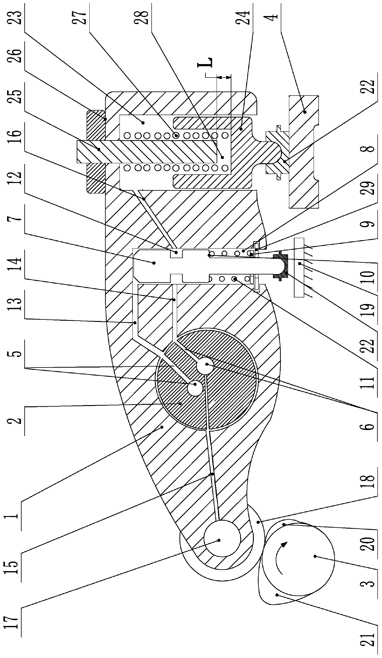
[0023] The present invention will be further described below with specific embodiment, see figure 1 :

[0024] An auxiliary braking rocker arm structure directly driven by hydraulic pressure. The rocker arm 1 is set on the rocker arm shaft 2. One end of the rocker arm 1 is in contact with the exhaust cam 3 through a transmission mechanism, and the other end of the rocker arm 1 is provided with a braking mechanism. , the bottom of the brake mechanism is provided with the exhaust valve bridge 4 or the valve, the brake mechanism controls the action of the exhaust valve bridge 4 or the valve, and the rocker arm shaft 2 is provided with the first brake oil passage 5 and the first lubricating oil The passage 6 , the first brake oil passage 5 and the first lubricating oil passage 6 all include an oil passage arranged axially along the rocker shaft 2 and an oil passage arranged radially along the rocker shaft 2 . An oil control valve is arranged on the rocker arm 1 between the rocker...


PUM


Abstract

The invention belongs to the technical field of engines, in particular to a direct-hydraulic-driven auxiliary brake rocking arm structure. The structure comprises a rocking arm, a rocking arm shaft, a transmission mechanism, an exhaust cam and a brake mechanism; an exhaust door bridge or a valve is arranged under the brake mechanism; an oil control valve is arranged on the rocking arm between the rocking arm shaft and the brake mechanism; the rocking arm is provided with a brake oil way for communicating the rocking arm shaft and the top of a valve cavity, a lubricating oil way for communicating the rocking arm shaft, the oil control valve rod and the brake mechanism, and a lubricating oil way for communicating the rocking arm shaft and the transmission mechanism; and the oil control valve controls connection and disconnection between the first lubricating oil way and the brake mechanism. The structure is simple, low in transformation cost and convenient to install, and can add an auxiliary braking function on the rocking arm to prolong the life of the brake mechanism of a whole vehicle and to improve the safety and the reliability of the whole vehicle in the downslope process.

Description

Technical field: [0001] The invention belongs to the technical field of engines, in particular to an auxiliary braking rocker arm structure directly driven by hydraulic pressure. Background technique: [0002] Engine braking techniques are well known in the prior art. A precedent for an engine braking device is the hydraulic engine brake disclosed in US Patent No. 3,220,392 by Cummins in 1965. The engine brake in this technology transmits the mechanical input through a hydraulic circuit to the exhaust valve to open. The above engine braking process is to temporarily convert the engine into a compressor to achieve engine braking. The fuel is cut off during the conversion process, and the exhaust valve is opened at the end of the engine piston compression stroke to allow the compressed gas (air during braking) to be released. The energy absorbed by the engine during the compression stroke cannot be used in subsequent expansion. The stroke returns to the engine pistons, but ...

Claims


Application Information

Patent Timeline
Patent Type & Authority Applications(China)
IPC IPC(8): F01L13/06F01L1/18F01L1/24
CPCF01L1/181F01L1/24F01L13/06
Inventor 俞展亮关大众曹中基柯雨辰赵阔姜义泉周道洋
Owner ZHEJIANG KANGHE MECHANICAL ENG CO LTD
Why Eureka
Try Eureka