
Broad-width type air source heat pump device
An air source heat pump, wide-width technology, applied in the field of refrigeration and heating, can solve the problem of unable to meet the heating demand in winter
- Summary
- Abstract
- Description
- Claims
- Application Information
AI Technical Summary
Problems solved by technology
Method used
Image

Examples
Embodiment Construction
[0030] Hereinafter, in conjunction with the accompanying drawings, the preferred embodiments of the present invention and its modified examples will be described in detail by way of illustration rather than limitation of the scope of protection required by the inventive idea.
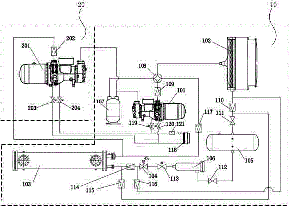
[0031] figure 1 It is a schematic diagram of the working principle of the wide-width air source heat pump device of the present invention. The wide-width air source heat pump device of the present invention mainly includes: a medium-high temperature refrigeration and heating system 10 and a low-temperature refrigeration compressor group 20.
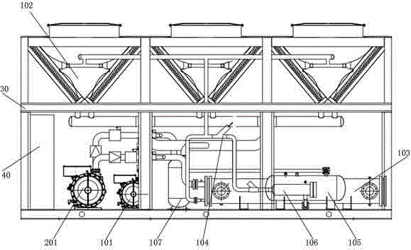
[0032] figure 2 It is a schematic structural diagram of the present invention, including a maintenance structure box 30, a medium-high temperature refrigeration and heating system 10, a low-temperature refrigeration compressor unit 20, and an electrical control system including an electric control box 40 are placed in the maintenance structure box 30.
[0033] figure 1 T...
PUM
 Abstract
Description
Claims
Application Information