Switch control device

A switch control and switching technology, applied to the power device inside the switch, electromagnetic relay details, relays, etc., can solve the problems of long distance, unsafe, cold, etc.

Inactive Publication Date: 2015-04-29
宁波保税区明德工业设计有限公司
View PDF6 Cites 2 Cited by
  • Summary
  • Abstract
  • Description
  • Claims
  • Application Information

AI Technical Summary

Problems solved by technology

[0002] The existing switches are generally turned on and off by manually pressing the button, and since the circuit wiring has been fixed in the initial decoration, and the position of the light switch cannot be changed when the distribution position of the home needs to be changed later, so After changing the position of the bed, the bed may be far away from the light switch. After turning off the light switch, you need to go to bed in the dark. It is not safe for people to go to bed in the dark. If it is winter, it is more likely to catch a cold

Method used


Image

  • Switch control device

Examples


Embodiment Construction

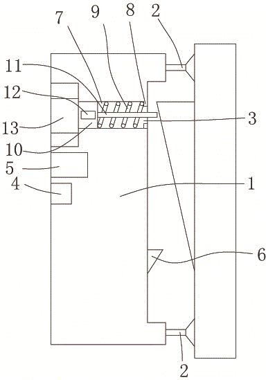
[0008] The present invention will be described in further detail below in conjunction with accompanying drawing and specific embodiment: see figure 1 , a switch control device, including a housing 1, a positioning device 2 is arranged on the housing 1, a pushing structure 3 for pushing the switch to be opened and closed is arranged on one side of the housing 1, and the pushing structure 3 includes a set There are two chutes 7 with openings on one side in the housing 1. A flange 8 is provided at the opening end of the chute 7, and a spring 9 is arranged in the chute 7 to lean against the flange 8, so that The other end of the spring 9 is supported by a slide block 10, the slide block 10 is provided with a push rod 11 towards the opening direction of the chute 7, the slide block 7 is provided with a magnet 12, and the chute 7 is closed. The end is provided with an electromagnet 13, and the electromagnet 13 is connected with a delayer 4, a power supply 5 and a toggle switch 6 in ...


PUM


Abstract

The invention discloses a switch control device. The switch control device comprises a shell, wherein a positioning device is arranged on the shell; a pushing structure used for pushing a switch to be switched on and off is arranged on one side of the shell; the pushing structure comprises two sliding slots which are formed in the shell; openings are formed in one side of each of the two sliding slots; flanges are arranged at the opening ends of the sliding slots; springs propped against the flanges are arranged at the interiors of the sliding slots; a sliding block is arranged at the other end of each spring in a propping manner; ejection rods are arranged on the sliding blocks in the direction facing towards the openings of the sliding slots; magnets are arranged on the sliding blocks; electromagnets are arranged at the closed ends of the sliding slots and are sequentially connected with a delayer, a power supply and a shifting switch; when the electromagnets are electrified, the electromagnets and the magnets mutually repel; the shifting switch is arranged on the other side of the shell; the shell is mounted on the switch; the shifting switch is switched off by the switch after the switch is pushed by the pushing structure. Through the adoption of the device, the problem that a person goes to bed in the dark after switching off the switch under the condition that the position of the switch is far from the bed can be solved.

Description

technical field [0001] The invention belongs to the technical field of switch control, in particular to a switch control device. Background technique [0002] The existing switches are generally turned on and off by manually pressing the button, and since the circuit wiring has been fixed in the initial decoration, and the position of the light switch cannot be changed when the distribution position of the home needs to be changed later, so After changing the position of the bed, the bed may be far away from the light switch. After turning off the light switch, it is necessary to go to bed in the dark. It is not safe for people to go to bed in the dark. If it is winter, it is more likely to catch a cold. Contents of the invention [0003] The present invention aims at the deficiencies of the prior art and provides a switch control device. This switch control structure can add a toggle switch device on the outside of the existing light switch and delay the toggle switch so ...

Claims


Application Information

Patent Timeline
Patent Type & Authority Applications(China)
IPC IPC(8): H01H47/18H01H50/16
CPCH01H3/28
Inventor 蔡明媚
Owner 宁波保税区明德工业设计有限公司
Why Eureka
Try Eureka