Optical fiber delay line structure having positive and negative delay function and method

A technology of optical fiber delay line and function, which is applied in the field of optical fiber delay line structure, can solve the problems of insufficient flexibility and achieve the effect of increasing the probability of success and increasing flexibility

Active Publication Date: 2015-07-22
ZHENGZHOU UNIVERSITY OF LIGHT INDUSTRY
View PDF6 Cites 0 Cited by
  • Summary
  • Abstract
  • Description
  • Claims
  • Application Information

AI Technical Summary

Problems solved by technology

[0004] The traditional fiber delay line structure can only p

Method used


Image

  • Optical fiber delay line structure having positive and negative delay function and method
  • Optical fiber delay line structure having positive and negative delay function and method
  • Optical fiber delay line structure having positive and negative delay function and method

Examples


Example Embodiment

[0018] The present invention will be further described in detail below in conjunction with the drawings and specific embodiments.

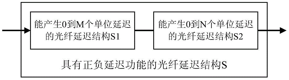
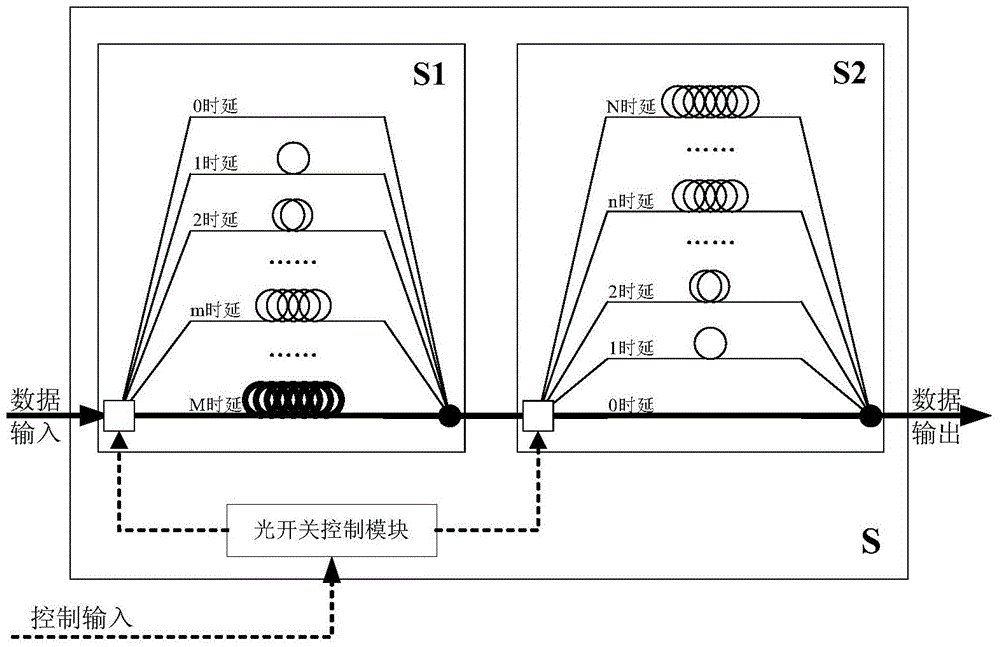
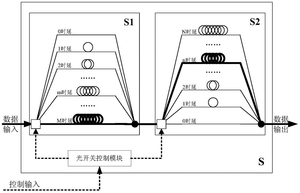
[0019] The specific implementation method of the present invention is to connect an ordinary optical fiber delay line structure S1 that can produce 0 to M unit delays and an ordinary optical fiber delay line structure S2 that can produce 0 to N unit delays in series to form a new optical fiber delay The line structure S, S1 and S2 exist as substructures of S, and are controlled by the optical switch control module in S. figure 1 It is a schematic diagram of the structure of a fiber delay line with positive and negative delay functions. It should be noted that the present invention only requires that S1 can produce a delay of 0 to M units, and S2 can produce a delay of 0 to N units, and there is no special requirement for their internal structure to be parallel, series or hybrid, but For clarity of description, the following takes the parallel structu...


PUM


Abstract

The invention discloses an optical fiber delay line structure having a positive and negative delay function and a method. A traditional optical fiber delay line structure S1 which can generate 0 to M unit delay and a traditional optical fiber delay lien structure S2 which can generate 0 to N unit delay are in series connection to form into a new optical fiber delay line structure S, the S1 and the S2 serve as sub-structures of the S and are unitedly controlled by an optical switch control module in the S. When the optical fiber delay lien structure is applied to the optical packet switched network and accordingly the flexibility of node switching is increased. When the optical fiber delay lien structure is applied to the optical burst switched network and accordingly the success probability of node reserve resources is increased.

Description

technical field [0001] The invention relates to the technical field of optical fiber delay lines, in particular to an optical fiber delay line structure and method with positive and negative delay functions. Background technique [0002] In the traditional optical network, the working mode of "optical transmission-electrical switching" is adopted, that is, data is transmitted in the form of optical signals in the link, and the optical signals are converted into electrical signals at nodes for switching processing, and then converted For the optical signal to be transmitted in the next link. This exchange method can be abbreviated as O-E-O (Optical-Electronic-Optical) exchange. In recent years, with the development of optical transmission technology, the improvement speed of nodes' processing capabilities in the electrical domain has been unable to keep up with the increase speed of optical link transmission capabilities, resulting in an "electronic bottleneck". In order to...

Claims


Application Information

Patent Timeline
IPC IPC(8): H04Q11/00H04L12/841
CPCY02D30/50
Inventor 袁俊岭丁汉清张启坤刘书如王锐芳
Owner ZHENGZHOU UNIVERSITY OF LIGHT INDUSTRY
Why Eureka
Try Eureka