Automatic decoking combustion chamber for combusting biomass fuel

A biomass fuel and combustion chamber technology, applied in combustion methods, combustion equipment, mobile grate, etc., can solve problems such as blocking the ventilation holes of the grate plate, reduce friction, facilitate friction matching, and achieve automatic coking efficiency. quick effect

Active Publication Date: 2015-11-11
张露纯
View PDF10 Cites 3 Cited by
  • Summary
  • Abstract
  • Description
  • Claims
  • Application Information

AI Technical Summary

Problems solved by technology

[0006] The technical problem to be solved in the present invention is to provide an automatic decoking combustion chamber for burning biomass fuel, which can be matched with biomass boilers or biomass burners to fill the gap in the market and effectively solve the problem of viscous combustion generated during the biomass combustion process. The problem of blocking the ventilation holes of the grate plate with jelly-like substances, and can evenly distribute the material, so that the biomass fuel can be fully burned

Method used


Image

  • Automatic decoking combustion chamber for combusting biomass fuel
  • Automatic decoking combustion chamber for combusting biomass fuel
  • Automatic decoking combustion chamber for combusting biomass fuel

Examples


Embodiment 1

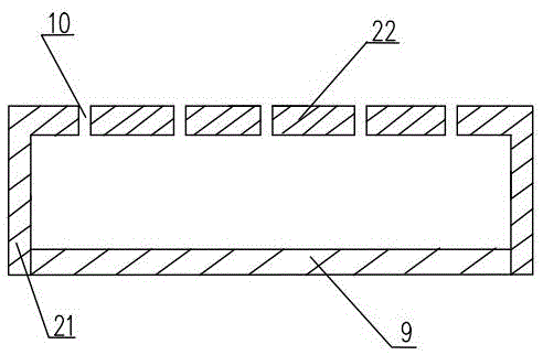
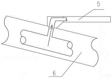
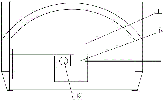
[0042] Such as Figure 1 to Figure 6 As shown, an automatic decoking combustion chamber for burning biomass fuel is used in conjunction with biomass burners, figure 1 The connecting flange 27 on the far right side can be connected to other related equipment. In this embodiment, the designed steam production rate is 6 tons / hour, and the burning fuel per hour is 900kg. It is a relatively large burner, including the grate located in the furnace 1 The grate plate includes a movable grate plate 5 and a fixed grate plate 4 fixed in the furnace. The movable grate plate 5 is frictionally matched with the fixed grate plate 4. The main bodies of the fixed grate plate 4 and the movable grate plate 5 are heat-resistant The groove-shaped metal cover plate made of metal material is made of heat-resistant cast iron in this embodiment. The groove-shaped cover plate is arranged in the furnace 1 poured by refractory concrete layer in the way of groove undercut. The groove-shaped cover plate In...

Embodiment 2

[0057] The difference between this embodiment and Embodiment 1 is that a water circulation system is arranged above the furnace of the combustion chamber, and it is used in a biomass boiler. This embodiment is designed to produce 2 tons of steam and burn 300 kg of fuel per hour, which is a relatively small boiler. The groove of its fire grate plate is not provided with sealing plate 9, and the plate leg 21 of fire grate plate is directly in frictional contact with the plate surface 22 of next fire grate plate, and fire grate plate comprises six fixed grate plates 4 and five movable ones. Grate plate 5, the vent hole 10 diameter of groove type fire grate plate is 7mm, is oblique hole, and the biomass fuel diameter that this combustion chamber selects is 9mm. The mobile bracket 6 is a rod type, and all the fixed grate plates 4 and the movable grate plates 5 share an air supply system, which includes an integral bellows arranged under all the grate plates and communicated with the...

Embodiment 3

[0059] The difference between this embodiment and Embodiment 1 is that a water circulation system is arranged above the furnace of the combustion chamber, and it is used in a biomass boiler. The design steam gas production is 1 ton, and the fuel can burn 150 kg per hour. It is a small boiler. The grate plate includes Four fixed grate plates 4 and three movable grate plates 5, the vent hole 10 diameter of groove type fire grate plate is 5mm, is oblique hole, and the biomass fuel diameter that this combustor selects is 8mm. The air supply pipeline of the movable grate plate 5 is the same as that of Embodiment 1. Each fixed grate plate 4 is only designed to supply air on one side, which is a one-way side air supply. The main pipe 17 is arranged on the lower side of the fixed grate plate 4, and the fixed grate plate There is no need to set a longitudinal cavity partition in the plate 4. There is only one fan. The air supply duct of the movable grate plate 5 is connected with the ma...


PUM


Abstract

The invention discloses an automatic decoking combustion chamber for combusting biomass fuel, and belongs to the technical field of combustion equipment. The automatic decoking combustion chamber for combusting the biomass fuel comprises movable grate plates arranged in a furnace and fixed grate plates fixed in the furnace, the movable grate plates move front and back and are in friction fit with the fixed grate plates, the fixed grate plates and the movable grate plates are alternately arranged in a stair-step mode and sequentially descend from a furnace mouth of the furnace to the back portion of the furnace, and all the movable grate plates act synchronously; each furnace grate plate comprises a groove-shaped metal cover plate, plate legs of the metal cover plate are in friction fit with the plate surface of the furnace grate plate below the metal cover plate, the plate surface of the furnace grate plate is provided with multiple air holes, and the lower surface of the furnace grate plate is provided with an air supply system which supplies air to the furnace through the air holes; the automatic decoking combustion chamber for combusting the biomass fuel is further provided with a hopper, a material pushing plate and an igniter. According to the automatic decoking combustion chamber for combusting the biomass fuel, the market vacancy is filled, the problem that sticky jelly-like matter generated in the combustion process of the biomass fuel blocks the air holes of the furnace grate plates is effectively solved, decoking is automatically performed, materials are distributed evenly, and full combustion is guaranteed; the automatic decoking combustion chamber is simple in structure and convenient and fast to operate.

Description

technical field [0001] The invention relates to an automatic decoking combustion chamber for burning biomass fuel, which belongs to combustion equipment technical machinery. Background technique [0002] In the process of utilizing biomass renewable energy, the combustion chamber for burning biomass fuel is particularly critical, and it can be matched with biomass boilers or biomass burners. my country's biomass boilers and biomass burners are developing rapidly. The development of biomass boilers and burners has become the most effective way to solve the problem of urban waste and waste crop straw. Lots of attention. [0003] Due to the wide variety of biomass fuels, the fuel has the characteristics of high water content (generally above 45%), more impurities (mixed with soil, fine sand), high ash content, and high alkali metal content. After the biomass fuel is burned in the furnace , easy to coke in the combustion chamber. Biomass coking mainly refers to the ash produce...

Claims


Application Information

Patent Timeline
Patent Type & Authority Applications(China)
IPC IPC(8): F23H11/22
Inventor 张占永
Owner 张露纯
Why Eureka
Try Eureka