Blade system, and corresponding method of manufacturing a blade system

A blade system and blade technology, applied in the field of blade devices, can solve problems such as expensive, difficult logic, and time-consuming

Inactive Publication Date: 2016-01-06
SIEMENS AG
View PDF15 Cites 4 Cited by
  • Summary
  • Abstract
  • Description
  • Claims
  • Application Information

AI Technical Summary

Problems solved by technology

On large turbines this is logistically difficult, expensive and time consuming

Method used


Image

  • Blade system, and corresponding method of manufacturing a blade system
  • Blade system, and corresponding method of manufacturing a blade system
  • Blade system, and corresponding method of manufacturing a blade system

Examples


Embodiment Construction

[0050] The illustrations in the drawings are schematic. It should be noted that similar or identical elements are provided with the same reference numerals in different figures.

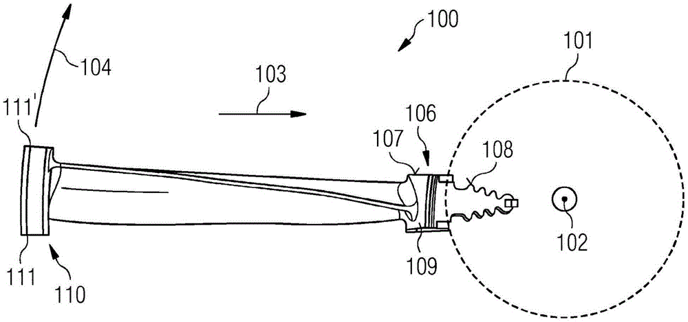
[0051] figure 1 A blade arrangement 100 for a gas turbine is shown. For better understanding, the extension and orientation of the features of the blade arrangement 100 are described with respect to a predefined direction of the rotor shaft 101 of the gas turbine (represented by dashed lines). The rotor shaft 101 includes an axial direction 102 parallel to the axis of rotation of the rotor shaft 101 . Furthermore, the radial direction 103 is depicted, which points to the central axis (rotation axis) of the rotor shaft 101 . The circumferential direction 104 is perpendicular to the axial direction 102 and the radial direction 103 . In the circumferential direction 104, a plurality of blade arrangements 100 may be arranged one after the other.

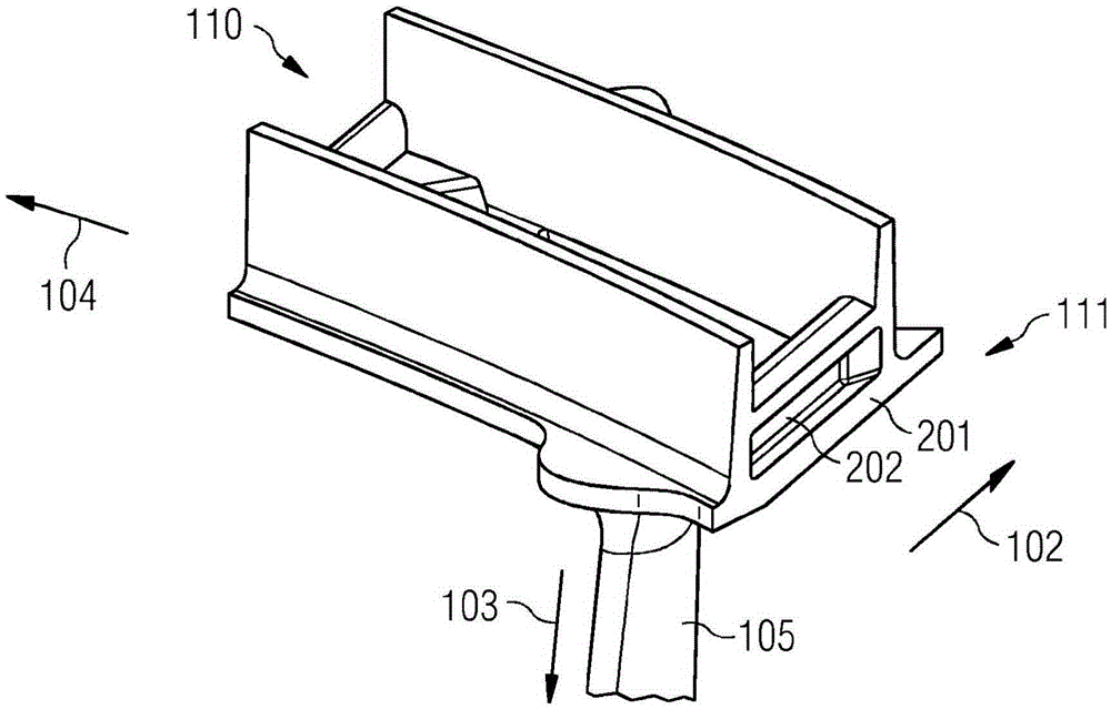
[0052] The blade arrangement 100 includes a shroud 1...


PUM


Abstract

Blade system for a gas turbine, the blade system comprising a blade device (100) and a further blade device (300), the blade device comprising a shroud (110), an airfoil (105) extending from the shroud (110) along the radial direction (103), wherein the shroud (110) comprises at a circumferential end (111) a wedge face (201), wherein the wedge face (201) comprises a recess (202) extending with a component along the axial direction (102), and a damping wire (401), wherein the damping wire (401) is arranged within the recess (202) such that the damping wire (401) is adapted for contacting the shroud (110) and a further wedge face (403) of a further shroud (310) of a further blade device (300) which is arranged adjacent to the shroud (110) along the circumferential direction (104), wherein the recess (202) comprises an inclining side surface (402) which comprises a normal (n) which is non-parallel with the radial direction (103), wherein the further wedge face (403) comprises a plane surface onto which the damping wire (401) is abuttable. A corresponding method of manufacturing a blade system is also provided.

Description

technical field [0001] The present invention relates to a blade arrangement for a gas turbine and a blade system for a gas turbine comprising the blade arrangement. Furthermore, the present invention relates to a method of manufacturing a blade system for a gas turbine. Background technique [0002] Turbine blades experience dynamic loading of the blade airfoil, resulting in deleterious vibration and high cycle fatigue. This is especially the case for so-called elongated blades, which are more prone to natural resonances interacting with the frequency of the load over the operating speed range of the turbine. Traditionally, this problem has been solved by providing a means of locking adjacent blades together at their shroud surfaces, and thus increasing the natural resonant frequency of the blades beyond the interaction during the normal speed range of the turbine. The blade shrouds have interlocking features with angled faces that force the blades to be assembled into a s...

Claims


Application Information

Patent Timeline
Patent Type & Authority Applications(China)
IPC IPC(8): F01D5/22F01D5/24F01D11/00
CPCF01D5/225F01D5/24F01D11/006Y02T50/60F01D5/3007F01D5/147F01D5/16
Inventor S·巴特M·麦克纳
Owner SIEMENS AG
Why Eureka
Try Eureka