
Clutch assembly with sensor unit and drive assembly with such clutch assembly

A technology of clutch components and drivers, applied in the direction of clutches, magnetic drive clutches, non-mechanical drive clutches, etc., can solve the problems of difficult maintenance, difficult assembly of sensors, etc., and achieve the effect of simple assembly

Active Publication Date: 2019-07-05
GKN AUTOMOTIVE INC
View PDF7 Cites 0 Cited by
  • Summary
  • Abstract
  • Description
  • Claims
  • Application Information

AI Technical Summary

Problems solved by technology

[0005] In the case of components according to the prior art, the sensors are often only difficult to assemble and difficult to reach in a repair situation (Servicefall)

Method used


Image

  • Clutch assembly with sensor unit and drive assembly with such clutch assembly
  • Clutch assembly with sensor unit and drive assembly with such clutch assembly
  • Clutch assembly with sensor unit and drive assembly with such clutch assembly

Examples


Embodiment Construction

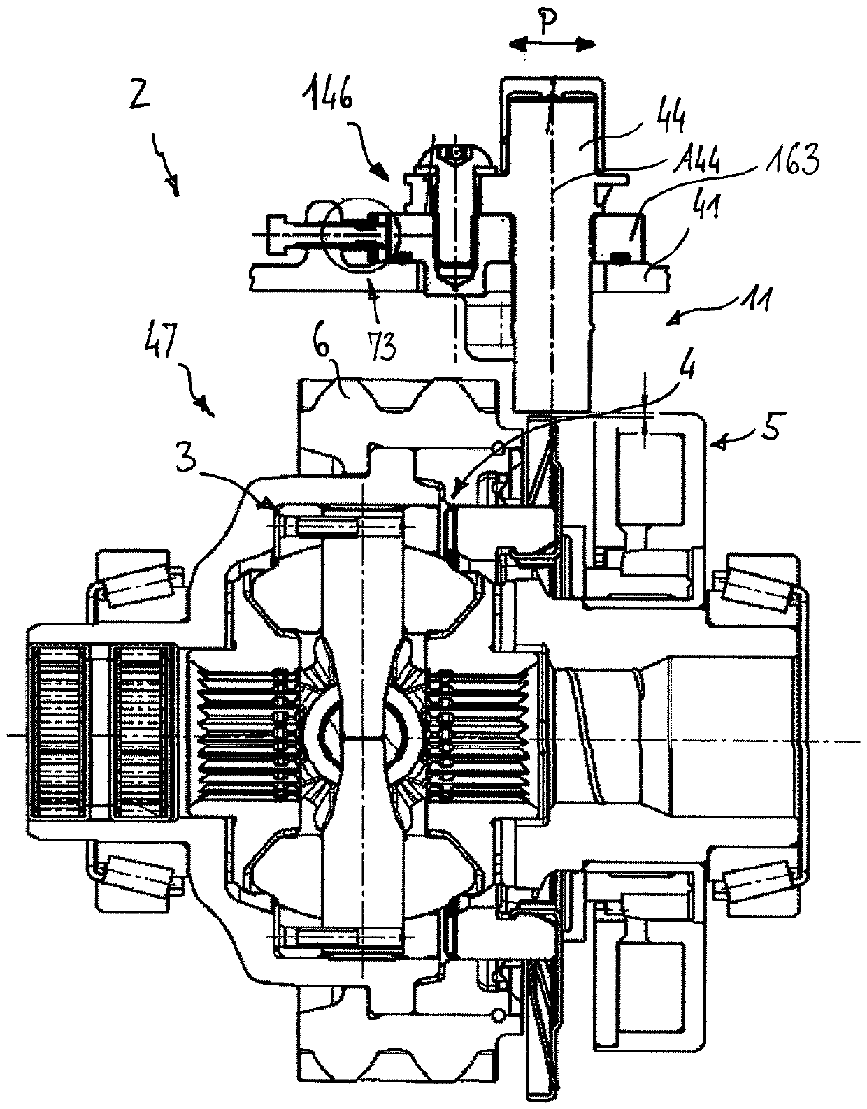
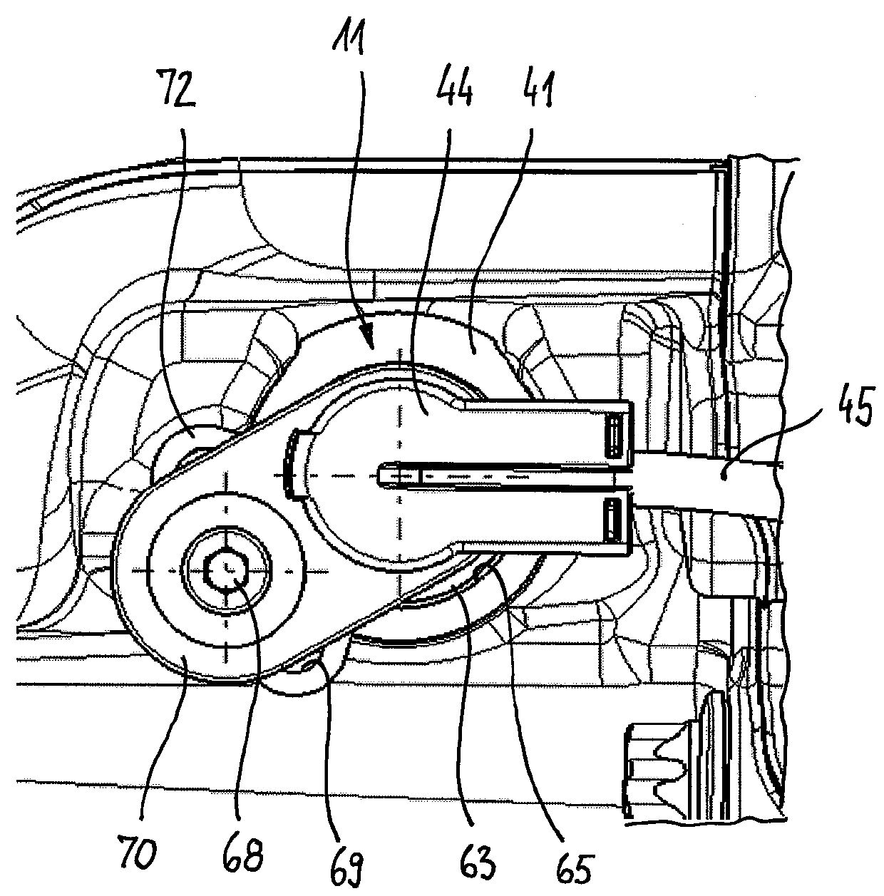
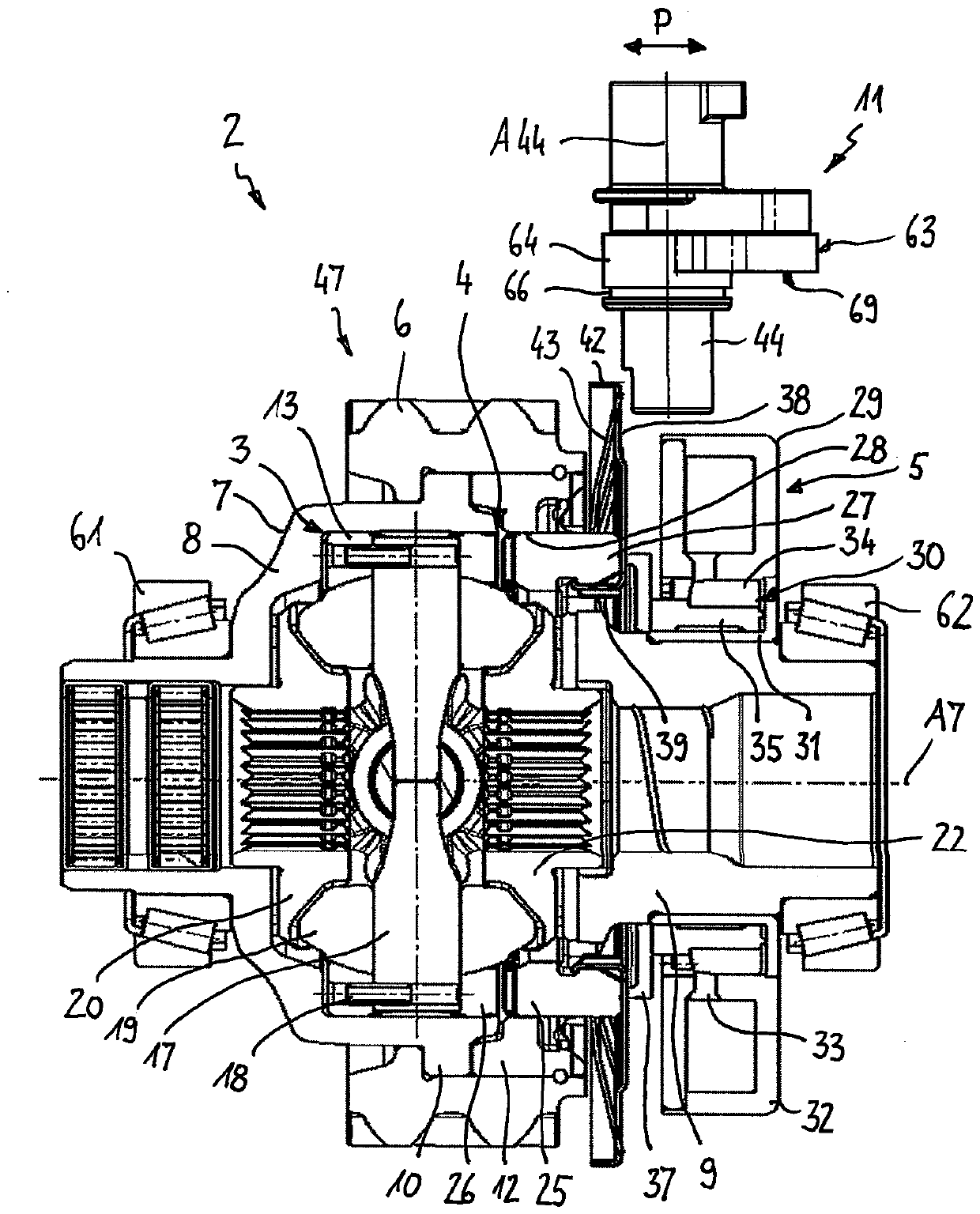
[0051] Figures 1 to 3 (which are described together below) shows a clutch pack 2 according to the invention in a first embodiment. The clutch pack 2 comprises a clutch 4 , an actuator 5 for actuating the clutch 4 and a sensor unit 11 . The clutch 4 can optionally transmit torque to the downstream transmission unit 3 in the power path. The gear unit 3 is designed in the form of a differential gear, but should not be restricted thereto. The clutch assembly 2 together with the transmission unit 3 , which together can also be referred to as a drive assembly 47 , is intended for use in the drive train of a motor vehicle, ie for distributing the introduced torque to two parts of the motor vehicle. on the two half shafts, wherein the torque transmission between the drive source of the motor vehicle and the half shafts can be optionally established or interrupted by means of the clutch 4 according to requirements. The clutch 4 is actuated by means of the actuator 5 , which acts on...


PUM


Abstract

A clutch assembly comprises a housing; a first drive part rotatingly drivable around an axis of rotation; a second drive part rotatable relative to the first drive part; a clutch which is arranged in the power path between the first drive part and the second drive part and which comprises a first clutch part which is connected to the first drive part in a rotationally fixed and axially movable way and a second clutch part which is drivingly connected to the second drive part; a controllable actuator for actuating the clutch; a sensor unit for determining a position signal which represents the axial position of the first clutch part, wherein the sensor unit comprises a target element which is at least indirectly connected to the first clutch part, and a sensor connected to the housing for recording a position of the target element; and adjusting means for adjusting the position of the sensor relative to the housing.

Description

technical field [0001] The invention relates to a clutch assembly, in particular for use in a drive train of a motor vehicle, with a clutch and a controllable actuator for actuating the clutch in such a way that a first clutch part and a second clutch part for torque transmission Optionally, they can be connected to each other or can be separated from each other again by opening. Such clutch assemblies are used to control torque transmission between a drive source and a drive shaft of the motor vehicle. The invention also relates to a drive assembly with such a clutch assembly and with a transmission unit, for example a differential transmission, which distributes the introduced torque to the two half-shafts of the drive shaft. Background technique [0002] A differential arrangement is known from DE 10 2009 056 088 A1 with drive wheels, a differential gear and a clutch which is arranged between the drive wheels and the differential gear. Furthermore, an electromagnetic ac...

Claims


Application Information

Patent Timeline
Patent Type & Authority Patents(China)
IPC IPC(8): F16D27/108F16D27/11F16H48/08F16H48/24
CPCF16D27/118B60K1/00B60K17/165F16D27/108F16D2300/18F16H48/08F16H48/24F16H48/34
Inventor J.豪普特J.雅各比F.西本汉德尔C.策尔斯H.赛德尔
Owner GKN AUTOMOTIVE INC
Learn More