Compact solenoid valve

Inactive Publication Date: 2008-11-13
EVERETT WILLIAM F +1
View PDF13 Cites 12 Cited by
  • Summary
  • Abstract
  • Description
  • Claims
  • Application Information

AI Technical Summary

Benefits of technology

[0006]The present invention overcomes the limitations of the prior art in solenoid valves by mounting the solenoid coil in an integrally formed magnetic material having a cross-sectional configuration resembling a bundt pan. Such a structure can be stamp-formed and creates an enlarged surface area available for the magnetic flux to the armature at the bottom of the bundt cross-section. However, since the ends of the stamped structure are not relevant to the magnetic circuit, they can be left unfinished. A thin, flat plate armature and an axial flow valve assembly allows for low friction, low mass movement of the valve seal. Placement of the armature and solenoid across a small air gap provides a high force, very fast response time with mi

Problems solved by technology

Air gaps, multiple components, and spacing in the material of these arrangements tend to reduce the efficiency of the magnetic circuit.
Further, the surface area available to the core for exerting magnetic flux on the armature affects the efficiency of the magnetic circuit.
However, larger coils tend to have a slower actuation response time because of inductiye reactance when switching the coils on and off.
Accordingly, there have been disadvantages and difficulties in terms of cost of manufacture and operational success in previous attempts at making small solenoid valves, such as of a size that would fit within a conventional aerosol spray can, or similarly sized application, and be operable over an extended period of time on conventional batteries of a consumer acceptable size.
However, since the ends of the stamped structure are not relevant to the magnetic circuit, they can be left unfinished.
Unfortunately,

Method used


Image

  • Compact solenoid valve
  • Compact solenoid valve
  • Compact solenoid valve

Examples


Example

[0022]In each of the drawings, like parts are denoted by like numerical indicia. In preferred embodiments, the present invention is actuated by commercially available electrical controls suitable for the intended usage of the dispensing apparatus as a whole, taking into account the size of the apparatus, where it is placed in relation to usage, the intended users, etc. in a conventional manner. Such commercially available controls are not considered part of the claimed invention. Various pulsing controls suitable for the embodiments shown herein are of the type which have been sold by Tri-Tech, LLC of Mishawaka, Ind.

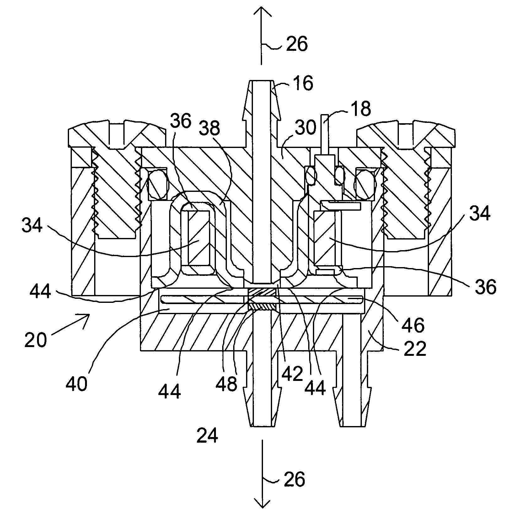
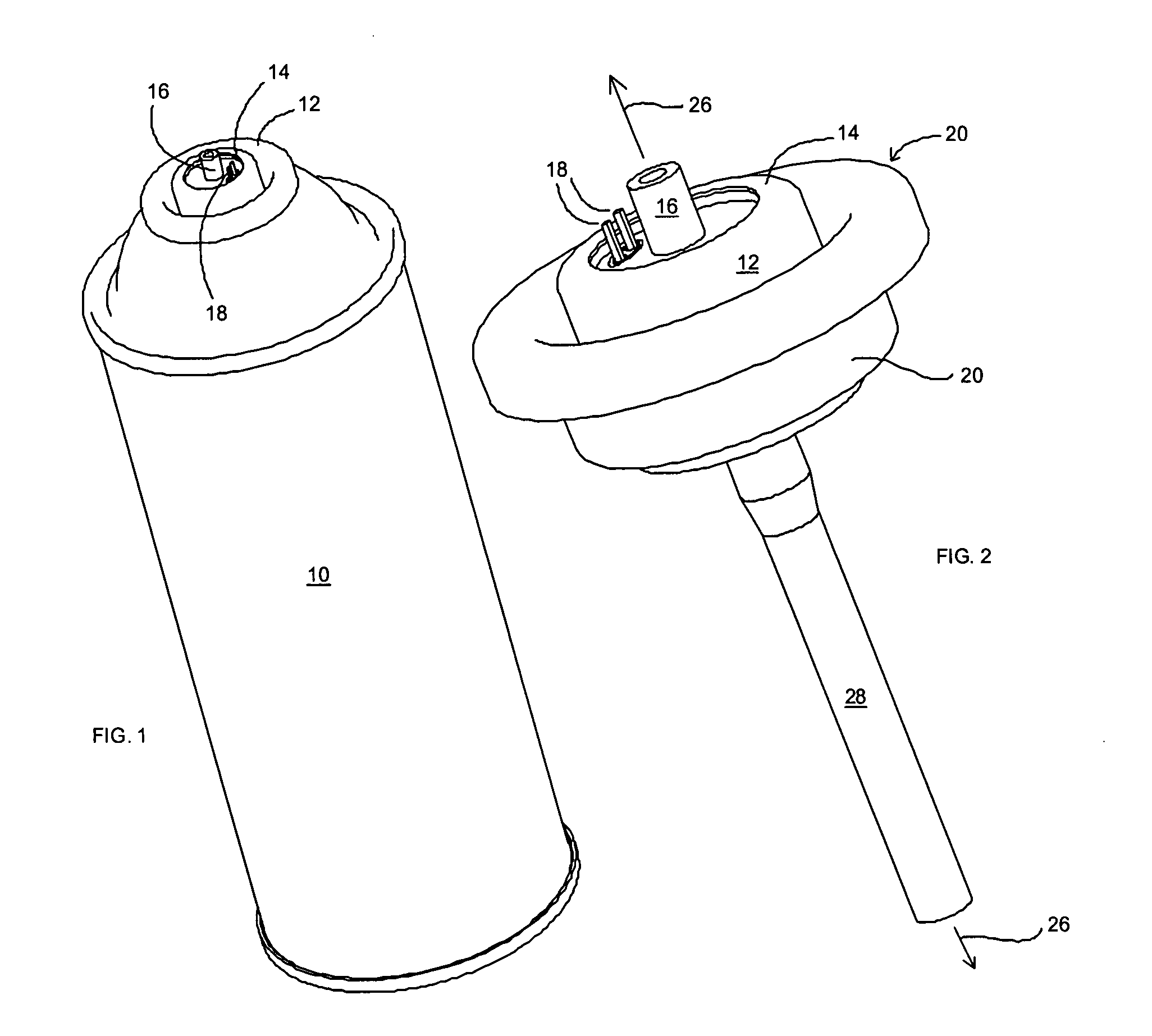
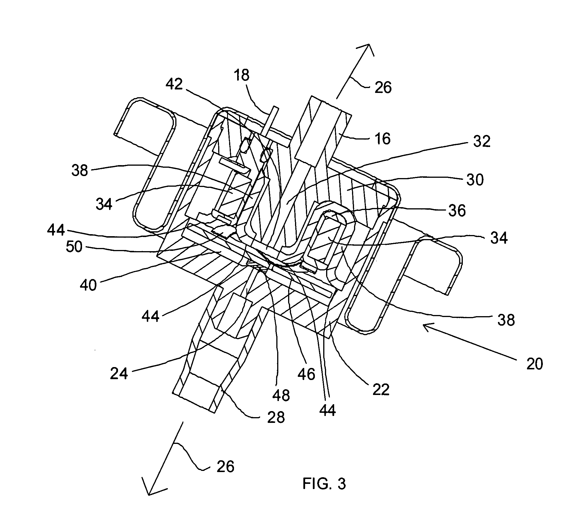
[0023]In general, FIGS. 1-3 relate to an internally mounted aerosol can version of the invention. FIG. 4 relates to an additional embodiment of an externally mounted aerosol can where the existing outset stem of the can seats onto the inlet of the invention apparatus, as for example, by an 0-ring seal connection. FIGS. 5 and 6 relate to three way ported valve configurati...


PUM


Abstract

A valve is provided having a solenoid coil in an integrally formed magnetic material having a cross-sectional configuration resembling a bundt pan. Such a structure can be stamp-formed and creates an enlarged surface area available for the magnetic flux to the armature at the bottom of the bundt cross-section. However, since the ends of the stamped structure are not relevant to the magnetic circuit, they can be left unfinished. A thin, flat plate armature and an axial flow valve assembly allows for low friction, low mass movement of the valve seal. Placement of the armature and solenoid across a small air gap provides a high force, very fast response time with minimal electrical power consumption.

Description

BACKGROUND AND SUMMARY OF THE INVENTION[0001]The present invention relates generally to solenoid valves and to apparatus for automatically dispensing a given quantity of fluid, such as from aerosol cans in a mist format, over an extended period of time.[0002]Solenoid valves generally control the flow of fluid in either liquid or gaseous form between an inlet and an outlet. Such valves have included an armature whose motion was controlled by switching on and off electric current to a coil mounted about a core formed of magnetic material. When the electricity was turned on, for example, the core became magnetized and attracted the armature toward it, thus opening a valve seal operably associated with the armature and allowing fluid to flow through the valve.[0003]The size and spacing of the core, coil, and armature elements determined the speed of actuation, the amount of electrical power needed for actuation and the cost of fabricating the structure. In general, in order to maximize ...

Claims


Application Information

Patent Timeline
IPC IPC(8): B65D83/14F16K31/10
CPCB65D83/14B65D83/262F16K31/0655
Inventor EVERETT, WILLIAM F.THAYER, JAMES R.
Owner EVERETT WILLIAM F
Why Eureka
Try Eureka