Deflection mechanism used for drilling machine and application method

A deflection mechanism and drilling rig technology, applied in drilling equipment and methods, drilling equipment, directional drilling, etc., can solve the problem that the adjustment of the position of the drilling arm can not achieve the desired effect, the position of the adjustment of the drilling arm is limited, and the rotation of the pin shaft is easy to wear and other problems, to achieve the effect of easy maintenance and maintenance, small friction and long service life

Inactive Publication Date: 2020-10-13
云南云内动力机械制造有限公司 +1
View PDF1 Cites 3 Cited by
  • Summary
  • Abstract
  • Description
  • Claims
  • Application Information

AI Technical Summary

Problems solved by technology

[0007] Aiming at the above-mentioned deficiencies in the prior art, the present invention provides a deflection mechanism for drilling rigs, which is used to solve the complex structure, poor stability, easy wear and tear of the pin shaft rotation in the prior art, and when the drill arm needs to When working in a special place, the adjustment of the position of the drill arm cannot achieve the desired effect, and the position of the drill arm adjustment is limited, etc.

Method used


Image

  • Deflection mechanism used for drilling machine and application method
  • Deflection mechanism used for drilling machine and application method
  • Deflection mechanism used for drilling machine and application method

Examples


Embodiment 1

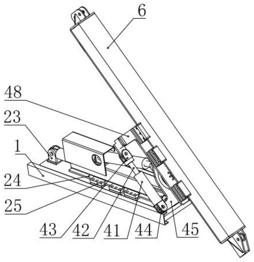
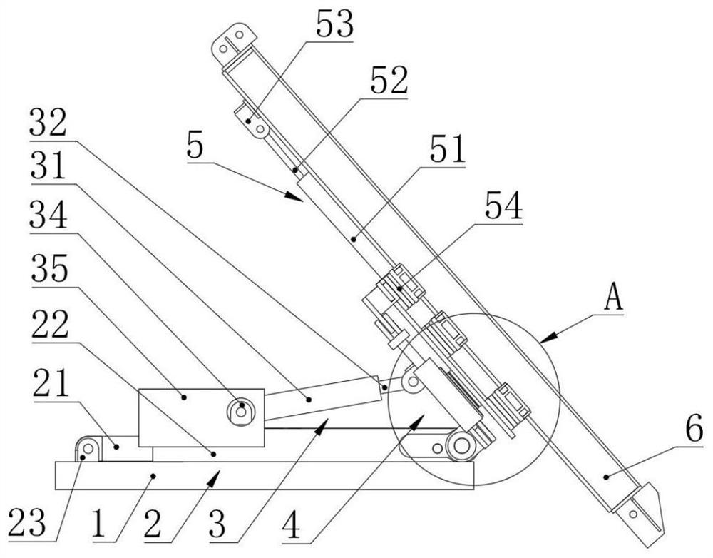
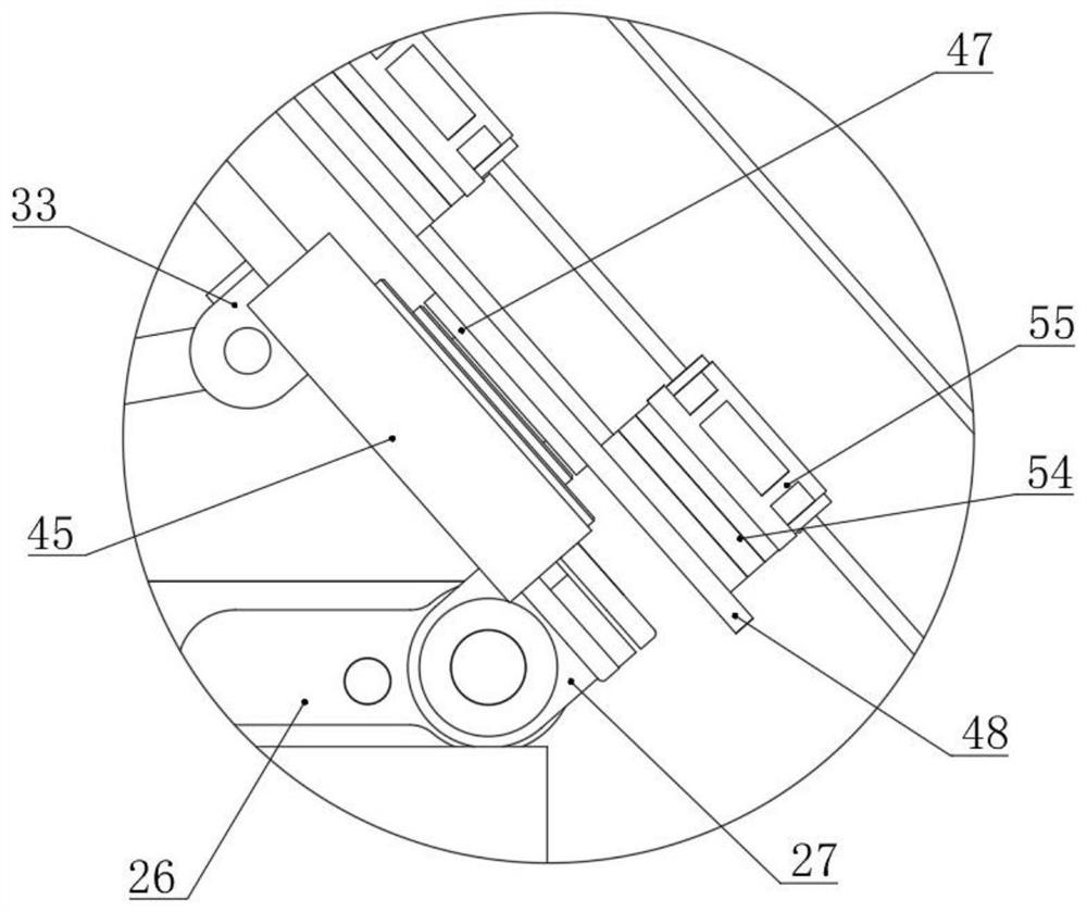
[0046] Such as Figure 1-4 As shown, a deflection mechanism for a drilling machine includes a base 1, a first sliding unit 2, an angle adjustment unit 3, a deflection unit 4 and a drill arm 6;

[0047] The first sliding unit 2 is arranged on the upper part of the base 2, the first sliding unit 2 is connected with the lower part of the deflection unit 4, and the first sliding unit 2 and the deflection unit 4 move synchronously; the angle adjustment unit 3 is installed on the upper part of the first sliding unit 2, the second A sliding unit 2 drives the angle adjustment unit 3 to perform synchronous movement, one end of the angle adjustment unit 3 is connected to the lower part of the deflection unit 4, the angle adjustment unit 3 drives the deflection unit 4 to flip relative to the base 1, and the drill arm 6 passes through the deflection unit 4 and the upper part of the base 1 connect.

[0048] When the present invention adjusts the spatial position of the drill arm 6, the fr...

Embodiment 2

[0058] This embodiment is a further improvement of the previous embodiment, such as Figure 1-4 As shown, a deflection mechanism for a drilling machine includes a base 1, a first sliding unit 2, an angle adjustment unit 3, a deflection unit 4 and a drill arm 6;

[0059] The first sliding unit 2 is arranged on the upper part of the base 2, the first sliding unit 2 is connected with the lower part of the deflection unit 4, and the first sliding unit 2 and the deflection unit 4 move synchronously; the angle adjustment unit 3 is installed on the upper part of the first sliding unit 2, the second A sliding unit 2 drives the angle adjustment unit 3 to perform synchronous movement, one end of the angle adjustment unit 3 is connected to the lower part of the deflection unit 4, the angle adjustment unit 3 drives the deflection unit 4 to turn over relative to the base 1, and the drill arm 6 passes through the deflection unit 4 and the upper part of the base 1 connect.

[0060] When the...


PUM


Abstract

The invention belongs to the technical field of drilling machines, and particularly relates to a deflection mechanism used for a drilling machine. The deflection mechanism comprises a base, a first sliding unit, an angle adjusting unit, a deflection unit and a drilling arm. The first sliding unit, the angle adjusting unit, the deflection unit and the drilling arm are all arranged on the upper portion of the base. The drilling arm is mounted above the deflection unit. The invention further relates to an application method of the deflection mechanism. The application method comprises the steps that firstly, the front-and-back position is adjusted; secondly, the vertical inclination angle is adjusted; thirdly, the deflection angle is adjusted; fourthly, the distance between a drill bit and the ground is adjusted; and fifthly, the drilling machine is made perpendicular to the construction ground. The deflection mechanism is simple in structure, convenient to operate, stable, reliable and long in service life, and when the drilling arm needs to work at a special place, the position of the drilling arm can be comprehensively adjusted.

Description

technical field [0001] The invention belongs to the technical field of drilling rigs, and in particular relates to a deflection mechanism for a drilling rig and a using method. Background technique [0002] During the drilling process of the drilling rig, it is necessary to drill holes on rocks or concrete. When a round hole needs to be drilled, a cylindrical drill bit is usually used, and the drill bit is provided with end teeth. Drilling rigs need to meet different work needs in different places. In order to adapt to the working environment with slopes, the drill pipe of the drilling rig needs to be deflected at a certain angle to ensure the pass rate of the hole. Driven by the drilling equipment, the drill bit can be The annular groove is drilled on the concrete, and when a certain depth is drilled, the cylindrical main body is pulled out, and the columnar concrete column is pulled out to complete the drilling operation. [0003] In the existing drilling equipment, front...

Claims


Application Information

Patent Timeline
Patent Type & Authority Applications(China)
IPC IPC(8): E21B7/06E21B7/02E21B15/04
CPCE21B7/02E21B7/06E21B7/062E21B7/064E21B15/045
Inventor 张思泽蒋佳陈友才陈帅文奎徐本春杨金美谭俊湘刘智杰李金牛泽良吴威王润朱玉江王先阳申时权
Owner 云南云内动力机械制造有限公司
Why Eureka
Try Eureka