Instrument break valve with lower valve stem non-rotation sealing structure

A technology of stop valve and valve stem, which is applied in the direction of valve shell structure, shaft seal, valve operation/release device, etc. It can solve the problems of small friction coefficient, easy wear, large friction force and friction coefficient, etc., and achieve friction and Small amount of frictional movement, long life, and excellent sealing performance

Inactive Publication Date: 2009-02-18
江苏星河集团有限公司 +1
View PDF0 Cites 3 Cited by
  • Summary
  • Abstract
  • Description
  • Claims
  • Application Information

AI Technical Summary

Problems solved by technology

[0003] In order to overcome the disadvantages of large friction force, friction coefficient and easy wear of the filling sealing part of the existing instrument stop valve, the present invention provides a non-rotating lower valve stem double sealing structure, which has a small friction coefficient, long service life and easy operation.

Method used


Image

  • Instrument break valve with lower valve stem non-rotation sealing structure
  • Instrument break valve with lower valve stem non-rotation sealing structure

Examples


Embodiment Construction

[0014] The present invention will be further described below in conjunction with the accompanying drawings and embodiments.

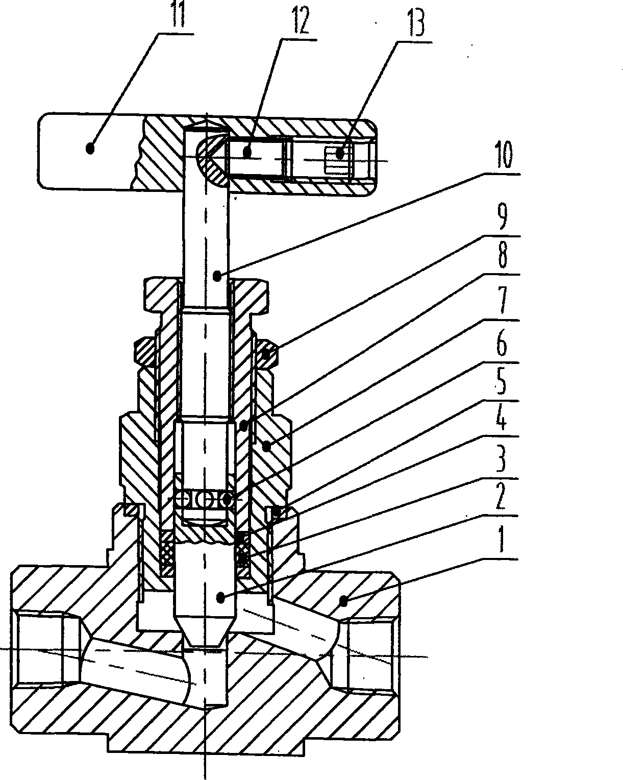
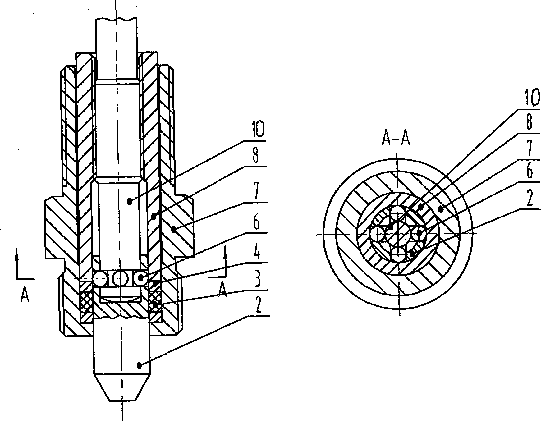
[0015] An instrument globe valve with a non-rotating and sealed structure of the lower valve stem, which consists of a valve body (1), a valve cover (7), a lower valve stem (2), a packing (3), a threaded guide sleeve (8), an upper valve stem ( 10) and other components, such as figure 1 shown. Its characteristics are: one end of the lower valve stem (2) is a valve core, the other end is a hole, the bottom of the hole is a plane, and 3 to 6 small holes are evenly distributed on the corresponding positions of its circumference; the lower part of the upper valve stem (10) The end face is arc-shaped, and it is inserted into the hole of the lower valve stem (2), so that the arc end face is in contact with the bottom plane of the hole, which is not only conducive to the uniform distribution of the force in the center of the lower valve stem (2), but also help...


PUM


Abstract

The invention provides an instrument stop valve with a non-rotary lower valve rod seal structure, which is widely applied to the industrial pipelines and is characterized in that one end of the lower valve rod is the valve core; the other end is a hole; a plurality of pores are evenly distributed on the circumference of the hole; the ditch groove end of the upper valve rod is inserted into the hole of the lower valve rod; a steel ball is respectively loaded into the ditch groove through each pore and screwed into a thread guide sleeve to form the steel ball flexible connection structure; the filler, the mounted upper valve rod and the lower valve rod are mounted into the valve cover and screwed into the thread guide sleeve to push the filler cushion to enable the filler to be pressed tightly between the lower valve rod and the valve cover, so as to form the filler seal structure. The valve cover is threaded through the seal washer to be screwed into the inner thread of the valve body and tightly sealed; a handle or a hand wheel is mounted on the top part of the upper valve rod; the handle or the hand wheel is rotated to drive the upper valve rod to lift spirally; under the effect of the steel ball flexible connection structure, the lower valve rod is prevented from rotating and moving up and down in the sealed filler so that the opening and closing of the valve are executed accordingly.

Description

technical field [0001] The invention relates to the design and manufacture of valves, which are widely used in industrial pipelines, especially the opening and closing and control devices of liquid or gas in various flow, differential pressure, pressure, liquid level and other instrument pipelines in automatic control. Background technique [0002] At present, the widely used instrument globe valves are sealed by the packing tightly hugging the valve stem. During operation, the handle or handwheel needs to be rotated to drive the valve stem to open and close directly under the action of the spiral lift inside the sealing packing. Because the valve stem The spiral lift produces a large friction force and friction coefficient in the sealing packing, so it is easy to wear and laborious to operate, which affects the service life and pressure-resistant sealing performance of the valve. Contents of the invention [0003] In order to overcome the disadvantages of large friction f...

Claims


Application Information

Patent Timeline
Patent Type & Authority Applications(China)
IPC IPC(8): F16K41/02F16K1/48F16K31/60F16K31/44F16K27/02
Inventor 朱义芳
Owner 江苏星河集团有限公司
Why Eureka
Try Eureka