High-pressure resistant three-valve group

A three-valve, high-pressure-resistant technology, used in lift valves, valve details, multi-way valves, etc., can solve the problems affecting the service life and pressure sealing performance of the valve, the operation cannot be carried out continuously, and the valve is damaged by high pressure scouring. Good strength, easy operation, and the effect of reducing the difficulty of installation

Inactive Publication Date: 2018-11-02
JIANGSU HUATAI ELECTRIC POWER ELECTRONICS INSTR
View PDF6 Cites 0 Cited by
  • Summary
  • Abstract
  • Description
  • Claims
  • Application Information

AI Technical Summary

Problems solved by technology

[0002] In the process of oil extraction, in industrial production such as underbalanced drilling, fracturing, and wellhead oil testing, it is necessary to use corresponding valves to control the fluid flow rate in the pipeline, and the downhole fluid is mostly high-pressure abrasive fluid. When the valve is opened, it will Cause high-pressure scouring damage to the valve, resulting in the inability to continue the oper

Method used


Image

  • High-pressure resistant three-valve group
  • High-pressure resistant three-valve group

Examples


Embodiment 1

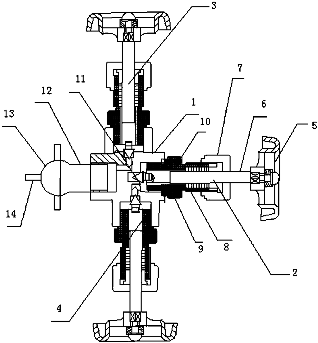
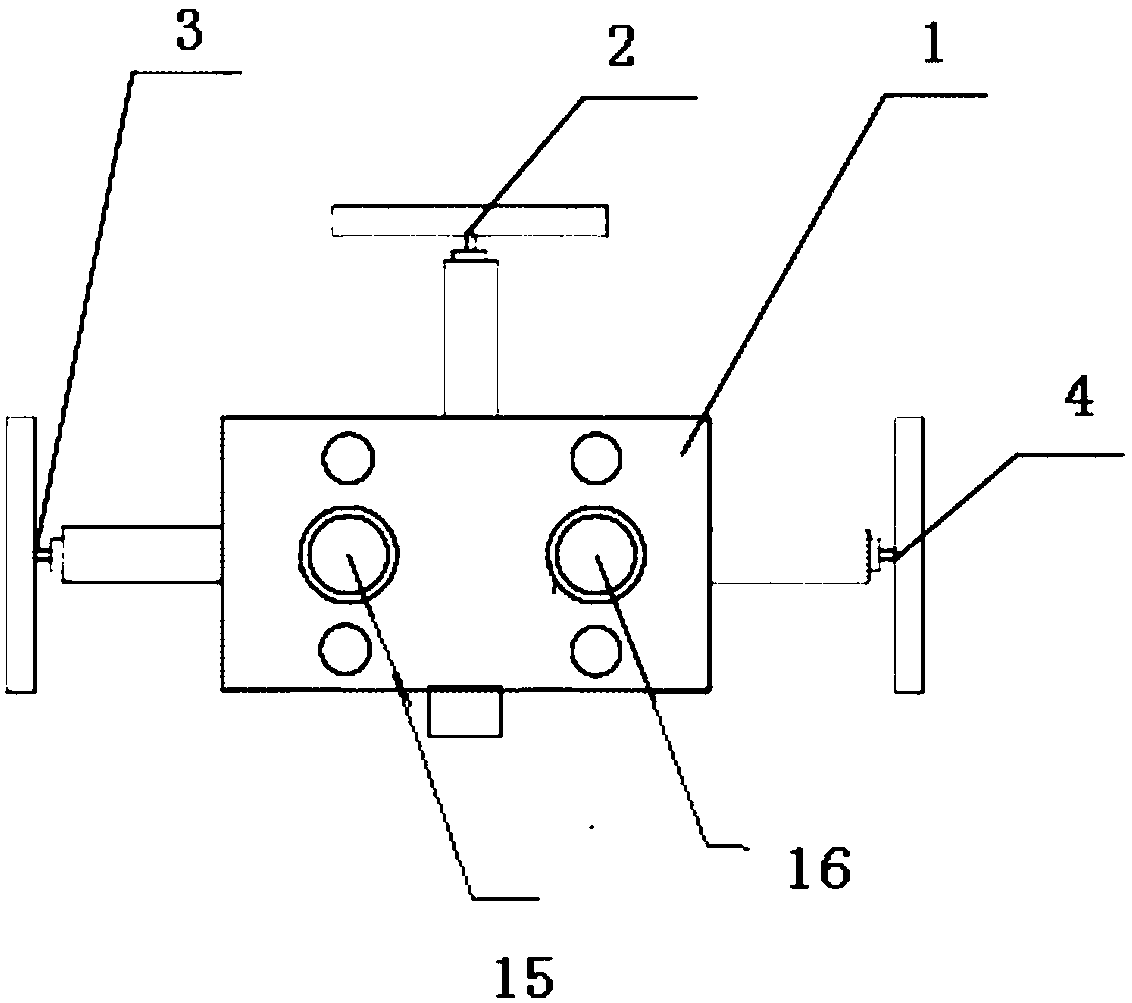
[0017] This embodiment provides a high-pressure three-valve group, such as Figure 1-2 Shown: including valve body 1, first control valve 2, second control valve 3 and third control valve 4, the first control valve is the main cut-off valve, the second control valve is the pressure relief valve, and the third control valve is the balance valve Valve, the valve body is a cuboid structure, the control valve connection port is provided in the middle of any three of the four sides of the valve body, and the medium inlet is provided on the end of the remaining side, the first control valve, the second control valve and the second control valve. The three control valves are respectively installed on the connection ports provided on the side of the valve body, and are used to control the cut-off or communication of each flow channel in the valve body. The second control valve and the third control valve are on the same axis, and the axis of the first control valve is perpendicular to ...


PUM


Abstract

The invention relates to a high-pressure resistant three-valve group. The high-pressure resistant three-valve group comprises a valve body, a first control valve, a second control valve and a third control valve. The valve body is of a cuboid structure. Middle positions of any three side surfaces of four side surfaces of the valve body are equipped with control valve connecting openings. The end surface on a remaining side is provided with a medium inlet which is equipped with a transfer ring. The first control valve, the second control valve and the third control valve are respectively installed on connecting openings arranged in the side surfaces of the valve body, which is used for controlling all flow passages of the valve body to be cut or communicated. Additionally, the first controlvalve, the second control valve and the third control valve share the same structure. The first control valve comprises a valve body, a valve rod, a handle, a joint and a valve clack. The end head onone side of the first valve rod is equipped with the handle. The outside of the valve rod is equipped with a press cover in a sleeving manner. The lower end of the press cover is equipped with a joint matching the connecting openings. The press cover is fixedly connected with the joint through a sealing ring. After the valve rod penetrates through the press cover and the joint, an end head on theother side of the valve rod is connected to the valve clack.

Description

technical field [0001] The invention relates to a high-pressure-resistant three-valve group. Background technique [0002] In the process of oil extraction, in industrial production such as underbalanced drilling, fracturing, and wellhead oil testing, it is necessary to use corresponding valves to control the fluid flow rate in the pipeline, and the downhole fluid is mostly high-pressure abrasive fluid. When the valve is opened, it will Cause high-pressure scouring damage to the valve, resulting in the inability to continue the operation. At present, the three-valve group of the instrument is sealed by the packing. Due to the spiral lift of the valve stem, a large friction force and friction coefficient are generated in the sealing packing. When the valve core There is still wear after repeated up and down movements, which will affect the service life and pressure-resistant sealing performance of the valve, and there will be a risk of leakage. Contents of the invention ...

Claims


Application Information

Patent Timeline
IPC IPC(8): F16K11/22F16K31/60F16K27/02F16K41/06F16K41/04F16K1/48F16K37/00F16K1/38
CPCF16K11/22F16K1/38F16K1/48F16K27/0263F16K31/60F16K37/0091F16K41/04F16K41/06
Inventor 陆超陈龙
Owner JIANGSU HUATAI ELECTRIC POWER ELECTRONICS INSTR
Why Eureka
Try Eureka