Device for blocking a transmission

A transmission mechanism and driving device technology, applied in transmission parts, transmission control, transmission box, etc., can solve the problems of cost, inability to clearly detect the locking state, and the inability to realize the absolute position recognition of the parking stop device, etc., to achieve low cost effect

Active Publication Date: 2020-02-07
ROBERT BOSCH GMBH
View PDF8 Cites 0 Cited by
  • Summary
  • Abstract
  • Description
  • Claims
  • Application Information

AI Technical Summary

Problems solved by technology

[0004] By designing the device for locking the transmission without a position sensor, the locked state cannot be unambiguously detected
The electronically commutated motor proposed as an alternative is, on the one hand, very expensive, but on the other hand, it does not allow absolute position detection for the parking brake

Method used


Image

  • Device for blocking a transmission
  • Device for blocking a transmission
  • Device for blocking a transmission

Examples


Embodiment Construction

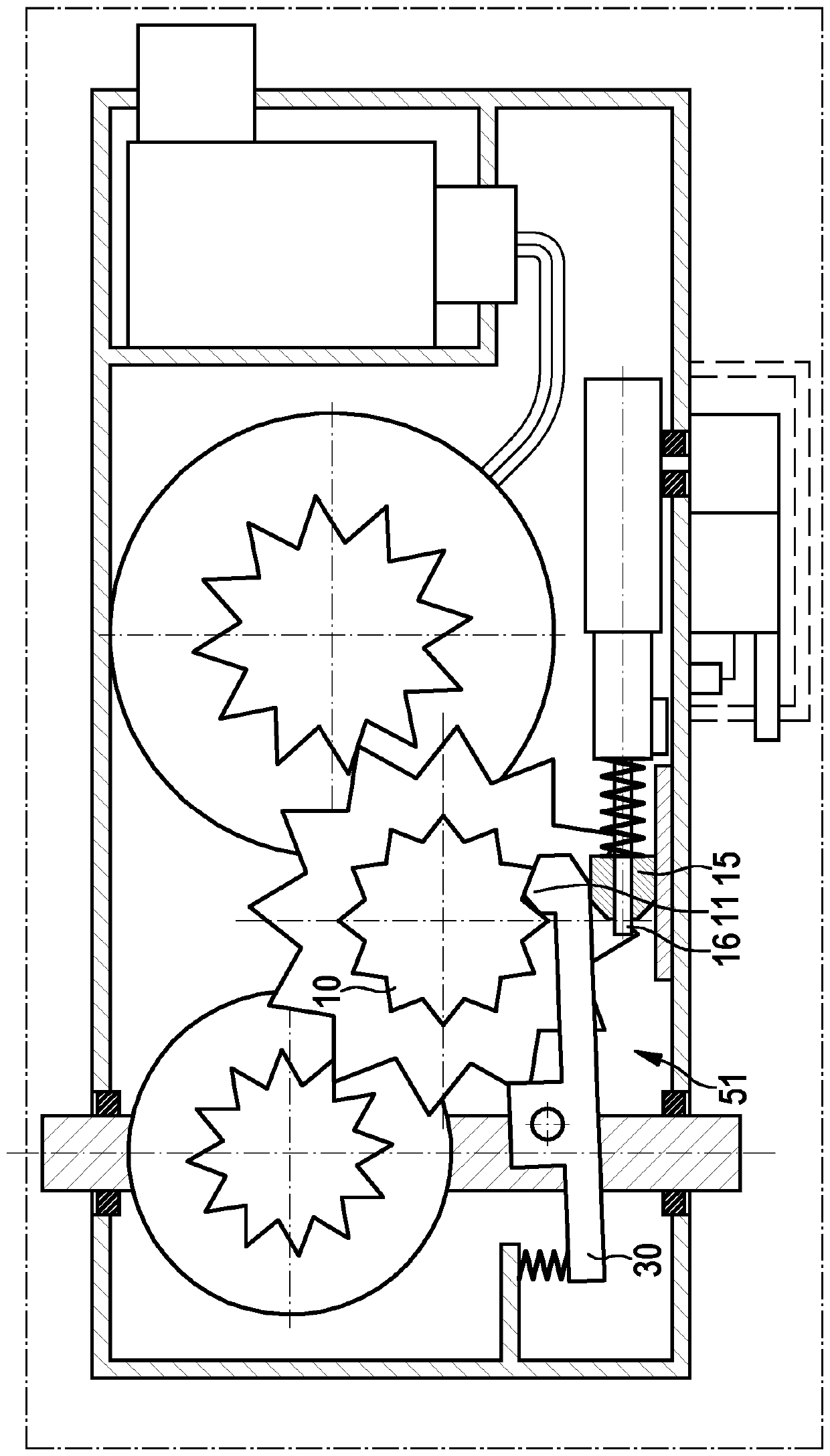
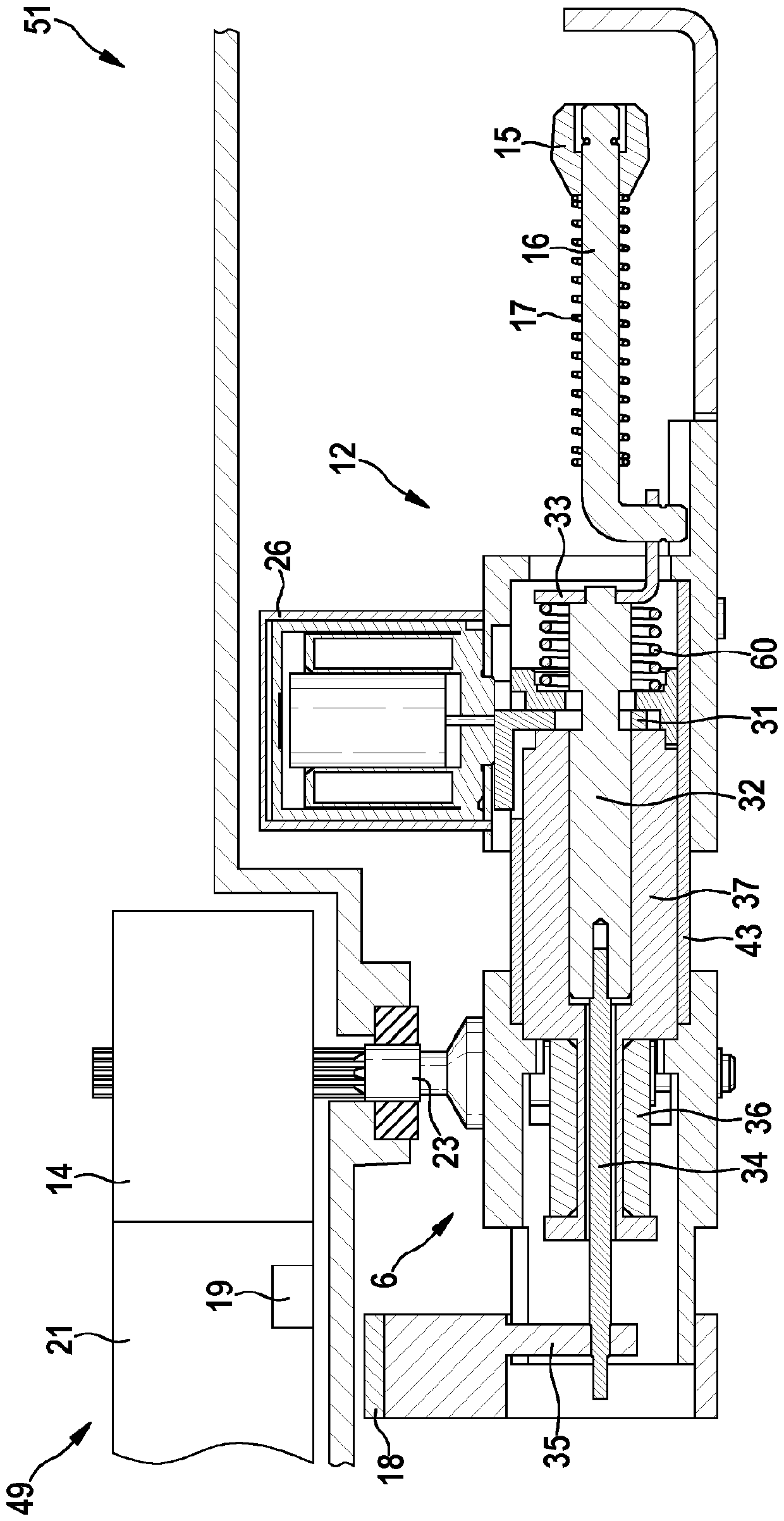
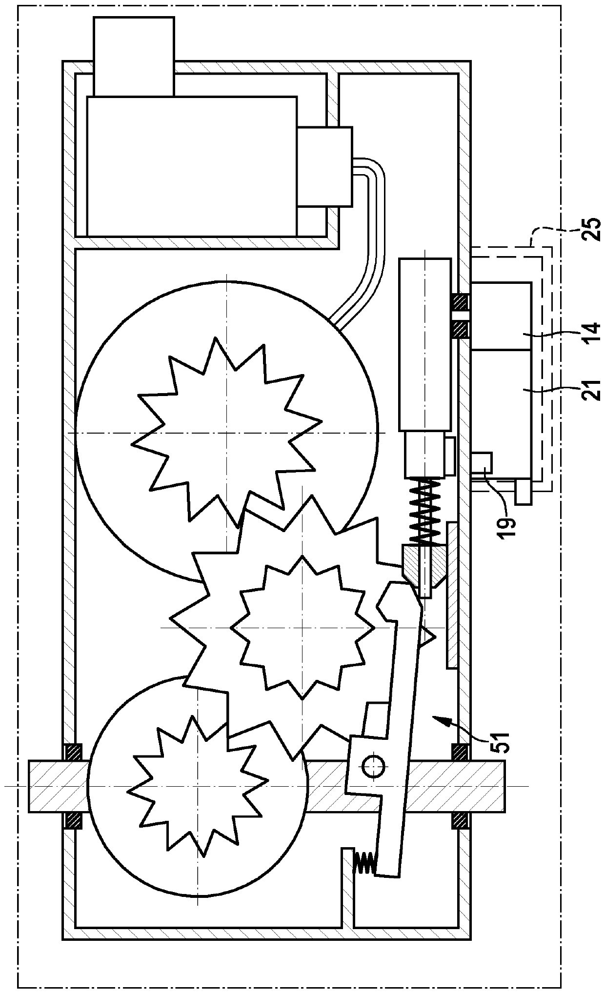
[0040] figure 1 A schematic diagram of a vehicle 48 with a drive unit 1 consisting of an electric motor 2 or an internal combustion engine 57 and a transmission 7 is shown. The vehicle 48 is shown schematically here as a multi-track vehicle, but can also be a single-track vehicle, such as, for example, an electrically driven motorcycle or a bicycle with an electric auxiliary drive. The electric motor 2 or the internal combustion engine 57 drives one or more drive wheels of the vehicle 48 via the transmission 7 . When using an internal combustion engine 57 , a transmission 7 is usually used with a plurality of switchable stages that can be switched either manually by the driver or automatically by a control device, ie without driver assistance. In a vehicle 48 equipped with an electric drive motor 2 , the transmission 7 with switchable stages can be largely dispensed with, so that no or very few switchable stages are usually used in the electric motor 2 Transmission mechanism...


PUM


Abstract

The present invention relates to a device for blocking a transmission comprising an actuation mechanism, which is arranged inside the transmission in an at least partially oil-filled transmission chamber, and a drive of the actuation mechanism, wherein the drive is arranged outside of the at least partially oil-filled transmission chamber.

Description

technical field [0001] The invention relates to a device for locking a transmission, for example for a vehicle transmission or for a transmission of a door drive, which device has a transmission for engaging (Einlegen) and disengaging (Auslegen). The actuating device of the blocking device connected to the output device and the emergency-run actuating device of the blocking device for engaging the transmission during emergency operation. Background technique [0002] In automatic transmissions for motor vehicles, the device for locking the transmission is used as a parking lock in order to prevent unintentional rolling of the parked vehicle. For this purpose, a locking wheel with toothed grooves is usually mounted in a rotationally fixed manner in the drive train, said locking wheel being locked or released by means of an actuatable locking pawl which positively engages in the toothed grooves. Rotary motion of the drive. When the selector lever of the automatic transmissio...

Claims


Application Information

Patent Timeline
Patent Type & Authority Applications(China)
IPC IPC(8): F16H61/00F16H63/34
CPCF16H61/0003F16H63/3466F16H63/3491F16H57/02F16H57/0457F16H61/0006F16H2057/02034F16H2057/02043
Inventor G.韦切尔I.德雷韦
Owner ROBERT BOSCH GMBH
Why Eureka
Try Eureka