Lidar device

A technology of laser radar and equipment, applied in the direction of optics, optical components, electromagnetic wave re-radiation, etc., can solve the problems that cannot meet the requirements of scratch resistance and durability, and achieve easy replaceability, good placement, and easy installation Effect

Pending Publication Date: 2022-03-11
ROBERT BOSCH GMBH
View PDF5 Cites 0 Cited by
  • Summary
  • Abstract
  • Description
  • Claims
  • Application Information

AI Technical Summary

Problems solved by technology

However, these fall far short of the requirements for scratch resistance and durability in wiping operations

Method used


Image

  • Lidar device
  • Lidar device
  • Lidar device

Examples


Embodiment Construction

[0035] The central idea of ​​the invention is in particular to provide an improved lidar device, especially with regard to cleaning.

[0036] For conventional LIDAR devices, synthetic plastics, for example in the form of polycarbonate (PC) or polymethylmethacrylate (PMMA, "acrylic glass", "plexiglass"), are usually used as optical elements. These materials have some disadvantages with regard to the cleaning process, in particular they are neither mechanically nor chemically highly loadable and thus lose their high optical quality over time due to frequent cleaning processes. The efficiency of lidar devices can be significantly reduced in this way.

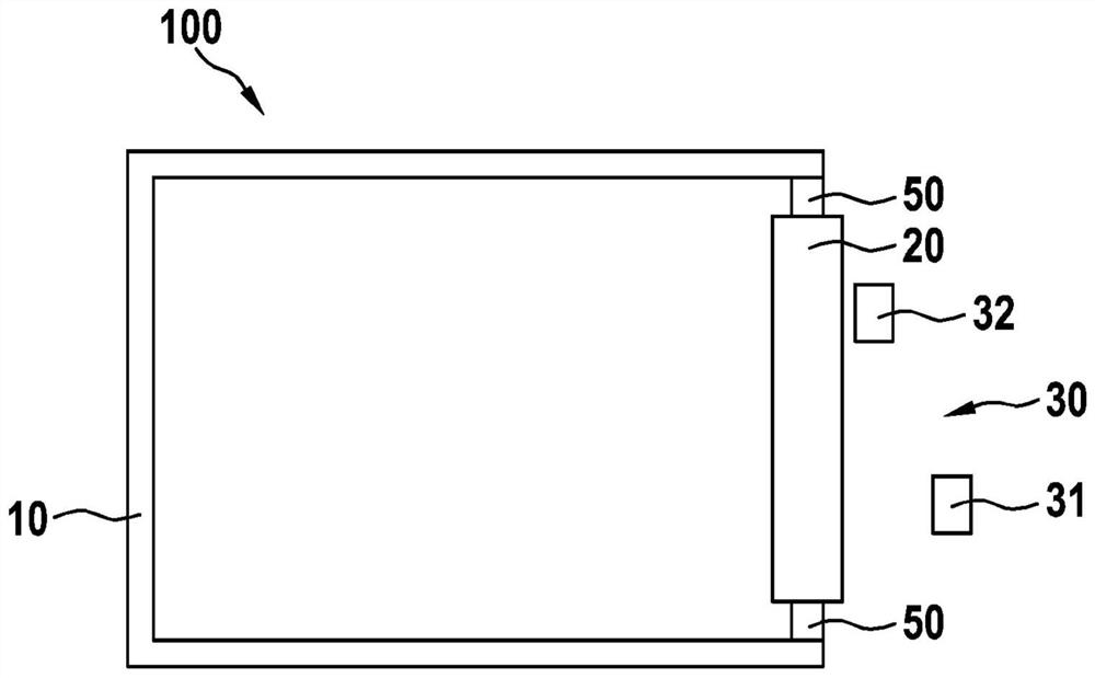
[0037] figure 1 A plan view of an embodiment of the proposed lidar device 100 is shown. The housing 10 can be seen, in which a first optical element 20 is arranged as an exit window in a side wall and thus directed outward. The first optical element 20 is made of a scratch-resistant and durable glass material and is configured s...


PUM


Abstract

A lidar device (100) has: a housing (10); and a first optical element (20) arranged in a side wall of the housing (10), substantially flat and made of glass.

Description

technical field [0001] The invention relates to a laser radar device. The invention also relates to a method for manufacturing a lidar device. Background technique [0002] In the coming years, LiDAR sensors will become established for highly automated driving functions on highways and in urban environments. A fundamental property of these sensors is that expected performance can only be achieved when the optical exit window to the surrounding environment is substantially free of contamination and / or obstructions. [0003] The detection of contamination and / or obstructions is known in principle and partially realized for many sensors today. However, for LiDAR sensors, the available solutions show significant weaknesses. For example, nozzles are common, by means of which an attempt is made to remove contamination at high pressure, wherein the cleaning effect is not always reliable and the water consumption is still very high. [0004] For small optical sensors, such as vi...

Claims


Application Information

Patent Timeline
Patent Type & Authority Applications(China)
IPC IPC(8): G01S7/481G01S17/931B08B1/00B08B3/08
CPCG01S7/481G01S17/931B08B1/006B08B3/08G01S7/4813G01S7/497G01S2007/4977G01S7/4817G02B27/0006
Inventor J·斯帕贝尔特M·拜尔
Owner ROBERT BOSCH GMBH
Why Eureka
Try Eureka