A non-self-resetting pressure relief electric pressure cooker
An electric pressure cooker and self-resetting technology, applied in pressure cookers and other directions, can solve the problems of inconvenient maintenance, large pressure relief area, and large destructive power, and achieve the effect of preventing unsafe cooking.
- Summary
- Abstract
- Description
- Claims
- Application Information
AI Technical Summary
Problems solved by technology
Method used
Image
Examples
no. 1 example
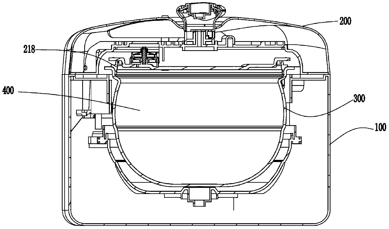
[0050] The present invention provides a non-self-resetting pressure relief electric pressure cooker, please refer to Figure 1-Figure 9, the electric pressure cooker includes a pot body 100, a pot cover 200 and an inner container 300, the inner container 300 is located in the pot body 100, the pot cover 200 is located on the pot body 100 and is connected with the inner container 300 An inner cooking cavity 400 is formed. When the food needs to be cooked, the user puts the food in the inner pot 300 .
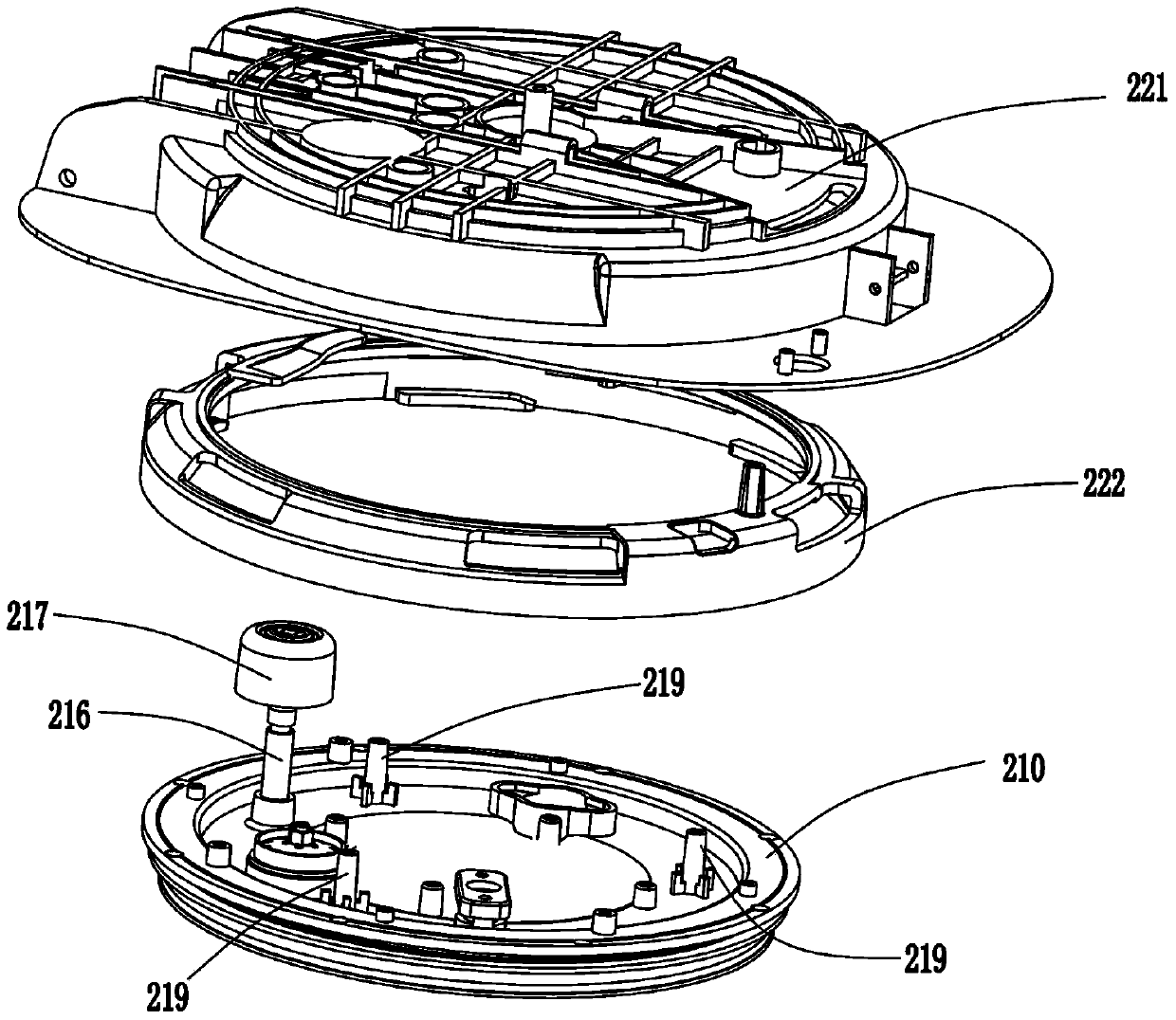
[0051] The pot cover 200 includes a lower cover 210 and an upper cover. In this embodiment, the lower cover 210 is an inner cover, and the lower cover 210 is provided with a second sealing ring 218, and the second sealing ring 218 is used for In order to seal the gap between the lower cover 210 and the inner tank 300, the upper cover is located above the lower cover 210. In this embodiment, the upper cover includes a lock ring 222, a lining 221 and a face cover. The inner linin...
no. 2 example
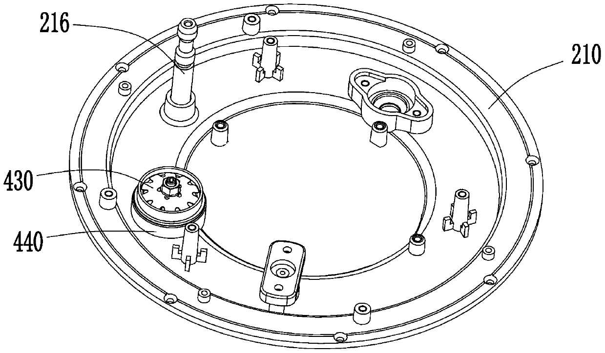
[0061] Figure 11 It is a perspective view of the lower cover of the second embodiment of the present invention, Figure 11 structure with Figure 3a The structures are similar, so the same element symbols represent the same elements. The main difference between this embodiment and the first embodiment is the fixing method of the elastic jumper.
[0062] In this example, see Figure 11-Figure 14 , the inner side of the sealing ring wall 440 is not provided with the first installation column 211, the periphery of the sealing ring wall 440 is provided with the second installation column 511 and the third installation column 512, the second installation column 511 and the third installation column The column 512 is formed by extending the lower cover 210 away from the inner cooking cavity 400, the second installation column 511 is located on opposite sides of the sealing ring wall 440, and the electric pressure cooker also includes a bridging piece 520, so Two ends of the brid...
no. 3 example
[0066] Figure 15 It is a perspective view of the lower cover of the third embodiment of the present invention, Figure 15 structure with Figure 3a The structures are similar, so the same reference numerals represent the same components. The main difference between this embodiment and the first embodiment is the shape of the elastic jumper and its fixing method.
[0067] In this example, see Figure 15-Figure 17 , the elastic jumping member is not the disc spring 430, the elastic jumping member is a jumping shrapnel 611, and the jumping shrapnel 611 is elongated and arched in the middle. In this embodiment, the inner side of the sealing ring wall 440 is not provided with the first mounting column 211, and the outer periphery of the sealing ring wall 440 is provided with a fourth mounting column 612, and the fourth mounting column 612 is formed by the lower cover. 210 is formed extending away from the inner cooking cavity 400 . One end of the jumping elastic piece 611 is a...
PUM
 Abstract
Description
Claims
Application Information
 - R&D
- Intellectual Property
- Life Sciences
- Materials
- Tech Scout
- Unparalleled Data Quality
- Higher Quality Content
- 60% Fewer Hallucinations
Browse by: Latest US Patents, China's latest patents, Technical Efficacy Thesaurus, Application Domain, Technology Topic, Popular Technical Reports.
© 2025 PatSnap. All rights reserved.Legal|Privacy policy|Modern Slavery Act Transparency Statement|Sitemap|About US| Contact US: help@patsnap.com


