

Hydraulic breaking hammer
A technology of hydraulic breaker and hydraulic hammer, which is applied in earth mover/excavator, construction, etc. It can solve the problems of large hydraulic impact, insufficient flow of full hydraulic hammer and gas-liquid hammer, and complex structure.
- Summary
- Abstract
- Description
- Claims
- Application Information
AI Technical Summary
Problems solved by technology
Method used
Image

Examples
Embodiment Construction
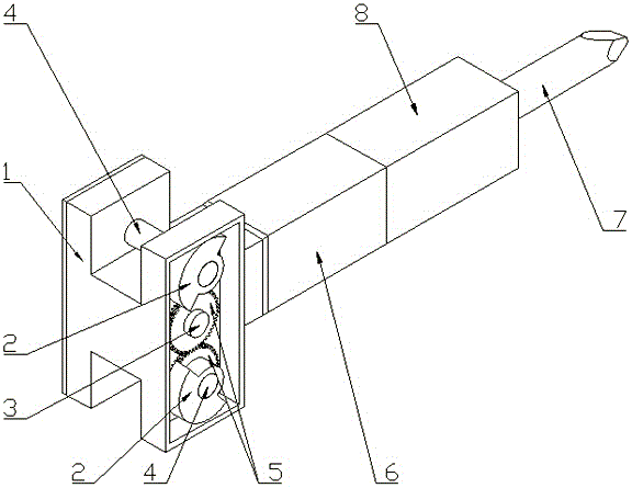
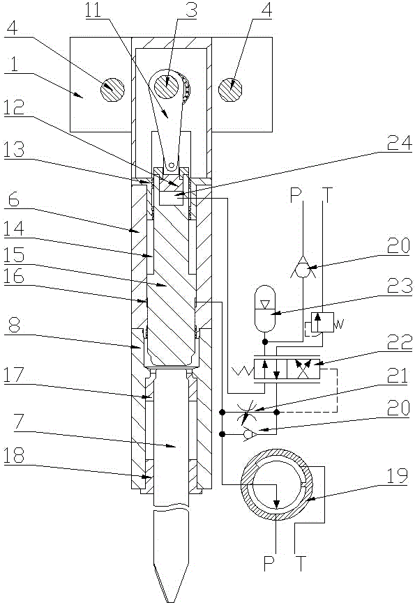
[0020] Main parts and components of the present invention:
[0021] 1. Crankcase 2. Eccentric wheel 3. Crankshaft 4. Eccentric wheel shaft 5. Gear 6. Cylinder block 7. Drilling rod 8. Drilling rod seat 11. Connecting rod 12. Connecting rod piston 13. Nitrogen chamber seal sleeve 14. Nitrogen chamber 15. Piston 16. Piston lower chamber 17. Drill rod rear sleeve 18. Drill rod front sleeve 19. Distribution plate 20. Check valve 21. Throttle valve 22. Reversing valve 23. Accumulator 24. Piston upper chamber.
[0022]At the moment of starting the hydraulic breaker, the piston 15 is at the farthest (dead point) from the crankshaft under the nitrogen pressure of the nitrogen chamber 14. At this time, the piston lower chamber 16 and the hydraulic motor (used to drive the crankshaft 3 ) through high-pressure oil, under the action of the hydraulic motor through the crankshaft 3 connecting rod 11 and the high-pressure oil in the piston lower chamber 16, the piston 15 performs the work pr...
PUM
 Abstract
Description
Claims
Application Information