Laser processsing system for processing workpiece with laser

A technology for laser processing and processed objects, which is applied in general control systems, laser welding equipment, metal processing equipment, etc., and can solve problems such as missed removal or correction of quality, product deformation, and step difference

Inactive Publication Date: 2016-02-03
FANUC LTD
View PDF3 Cites 3 Cited by
  • Summary
  • Abstract
  • Description
  • Claims
  • Application Information

AI Technical Summary

Problems solved by technology

[0008] First, there is a problem that the wall surface of the cutting groove is melted again and removed by re-irradiating the laser beam to the cut groove that has already been formed, and the cut surface becomes rough, or the re-melted workpiece solidifies on the bottom surface to generate scum (glitch)
Second, if the laser cutting is temporarily interrupted, the temperature of the workpiece will drop and thermal shrinkage will occur, which may cause a step difference in the cut surface of the workpiece at the position where the processing is resumed.
Third, due to the unstable processing, there may also be cutting residues that are not penetrated by laser cutting
[0011] However, when laser cutting is temporarily interrupted by a specific interruption command caused by an unexpected situation, and when the laser cutting is restarted, there may be leftover parts of cutting such as micro-joints.
In addition, it is difficult to distinguish the above-mentioned remaining part from the intentionally formed micro-joint processing part.
In addition, the position or shape of the remaining cutting formed by the specific interrupt command is not suitable, so when the product is taken out from the mother, it takes an unexpected large force on the remaining cutting part as described above, and the product may be deformed.
[0012] Also, in the remaining part of the cut formed by a specific interrupt command, although the grooving appears to be continuous from the surface of the workpiece, in fact, the grooving may not penetrate to the bottom. In this case, it is also difficult to see Interruption site
[0013] In addition, after the laser cutting is temporarily interrupted and restarted, when the workpiece containing the above-mentioned problem proceeds to the next process, an opportunity to remove or correct a low-quality product may be missed, and such a product may flow out.
In addition, it is also conceivable that the quality of the product will further decrease due to the above-mentioned processed object entering the next process.

Method used


Image

  • Laser processsing system for processing workpiece with laser
  • Laser processsing system for processing workpiece with laser
  • Laser processsing system for processing workpiece with laser

Examples


Embodiment Construction

[0033] Hereinafter, embodiments of the present invention will be described with reference to the drawings. In the following drawings, the same reference numerals are assigned to the same components. For easy understanding, the scales of these drawings are appropriately changed.

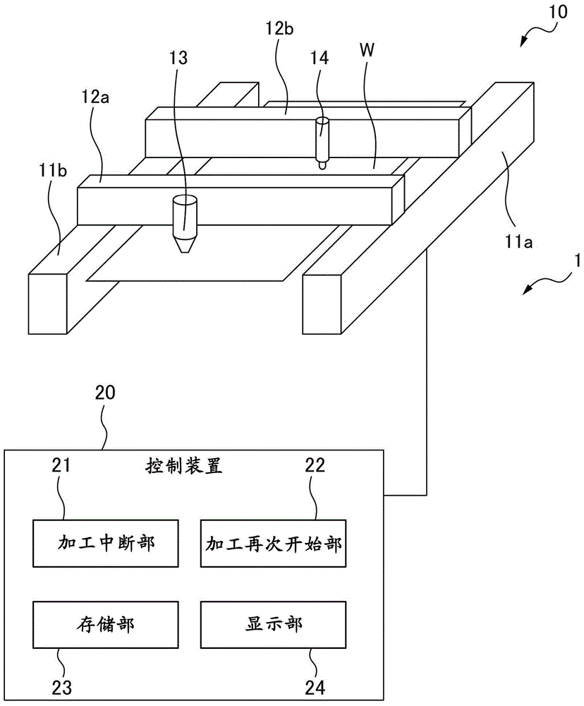
[0034] figure 1 It is a schematic diagram of the laser processing system based on 1st Embodiment of this invention. Such as figure 1 As shown, the laser processing system 1 mainly includes a laser processing machine 10 and a control device 20 for controlling the laser processing machine 10 . figure 1 The illustrated laser processing machine 10 is, for example, a laser cutting device. The laser processing machine 10 has two guide rails 11a, 11b parallel to each other, and a plate-shaped workpiece W is arranged between these guide rails 11a, 11b.

[0035] And, the positioning rails 12a, 12b perpendicular to the guide rails 11a, 11b are disposed above the guide rails 11a, 11b. The length of these p...


PUM


Abstract

A laser processing system that processes a workpiece with a laser includes a processing interruption unit that interrupts laser processing of the workpiece in accordance with an interruption signal, a processing resumption unit that resumes the laser processing of the workpiece after the interruption signal is cancelled, and an interruption point visualizer providing unit that provides the workpiece with an interruption point visualizer that allows an interruption point on the workpiece where the laser processing is interrupted by the processing interruption unit to be visually recognized.

Description

technical field [0001] The present invention relates to a laser processing system for performing laser processing on a workpiece. Background technique [0002] When processing a workpiece using a laser processing machine, processing may be interrupted by an instruction from an operator or a specific interruption command. Such a specific interrupt command is generated due to an unexpected situation such as a power failure or a decrease in the supply pressure of the laser gas. [0003] The laser processing machines described in Japanese Patent Laid-Open No. 2003-225783, Japanese Patent Laid-Open No. 2004-306073, and Japanese Patent Laid-Open No. 2010-120071 have the ability to resume processing even if the processing is interrupted as described above. processing restart function. [0004] However, when the laser processing is temporarily interrupted and the laser processing is restarted from the interrupted position, the processing quality is likely to be inferior to the nor...

Claims


Application Information

Patent Timeline
Patent Type & Authority Applications(China)
IPC IPC(8): B23K26/38B23K26/08B23K26/70
CPCB23K26/0876B23K26/38G05B19/4067G05B2219/31048G05B2219/37129G05B2219/50096G05B2219/45165Y02P90/02G05B19/182
Inventor 森敦西川佑司
Owner FANUC LTD
Why Eureka
Try Eureka