Propeller pumps for pumping liquids

A propeller, liquid technology, applied to the components of pumping devices for elastic fluids, liquid fuel engines, pumps, etc., can solve problems such as large losses, increased risk of reverse flow, etc.

Active Publication Date: 2017-12-26
XYLEM EURO GMBH
View PDF1 Cites 0 Cited by
  • Summary
  • Abstract
  • Description
  • Claims
  • Application Information

AI Technical Summary

Problems solved by technology

This depends primarily on the boundary layer along the surrounding surface of the pump core, which is added to the guide vanes in the region where the curvature radius of the convex suction side of the guide vanes starts to increase (as viewed in the axial direction) Boundary layer on the suction side, which overall leads to an additional increased risk of reverse flow and consequently large losses

Method used


Image

  • Propeller pumps for pumping liquids
  • Propeller pumps for pumping liquids
  • Propeller pumps for pumping liquids

Examples


Embodiment Construction

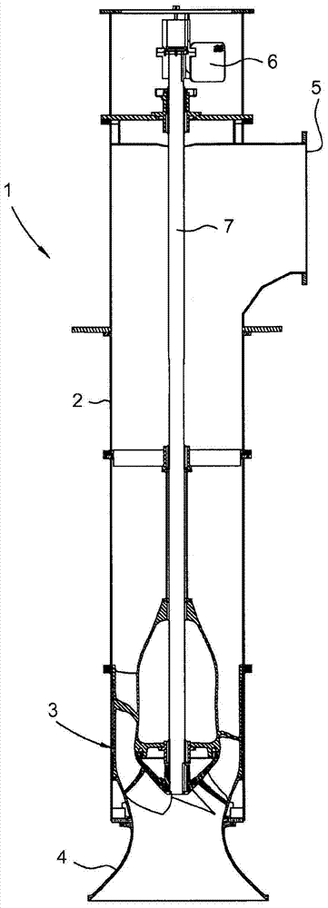
[0024] Referenced by way of the foreword figure 1 , which shows a propeller pump arrangement generally indicated by reference number 1 . The propeller pump arrangement 1 comprises: a housing pipe 2 having one or more segments; a propeller pump according to the invention generally designated with reference numeral 3 arranged in said housing In the lower end of the tube 2 ; an inlet funnel 4 connected to the lower end of the housing tube 2 ; an outlet 5 arranged in the upper end of the housing tube 2 ; and a drive unit 6 . In the illustrated embodiment, the drive unit 6 is located at a distance from the propeller pump 3 and outside the housing tube 2 and is connected to the propeller pump 3 by an axially extending drive shaft 7, however, it should be mentioned that the drive The unit 6 can be arranged in a suitable propeller pump 3 .

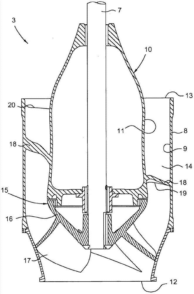
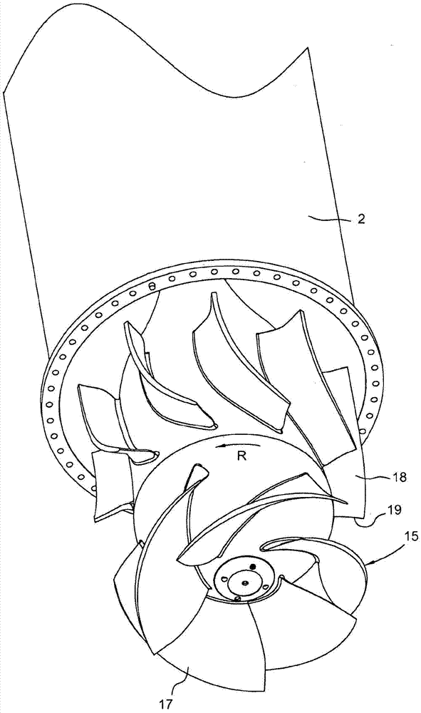
[0025] now also refer to Figure 2-Figure 4 , which shows a propeller pump 3 according to the invention. The propeller pump 3 is also known a...


PUM


Abstract

A propeller pump (3) for pumping liquids, said propeller pump comprising: an axially extending tubular pump casing (8) with an inner surface (9); an axially extending pump core ( 10), at least one axial section of the pump core (10) is surrounded by the pump housing (8), and the pump core (10) comprises a propeller (15) having a hub (16) and at least one blade (17); and at least one guide vane (18), said at least one guide vane comprising an upstream positioned leading edge (19) and a downstream positioned trailing edge (20), and said at least one guide wheel The vanes comprise a pressure side (PS) and a suction side (SS) in circumferential direction, said at least one guide vane (18) surrounded by the inner surface (9) of said pump casing (8) and the pump core (10) Extends between faces (11). At the leading edge (19) of the at least one guide vane (18), the distance between the suction side (SS) of the guide vane (18) and the surrounding surface (11) of the pump core (10) The connection angle (α) is greater than 90 degrees.

Description

technical field [0001] The present invention relates generally to a propeller pump for pumping liquids, and in particular to a semi-axial or diagonal flow pump, wherein incoming liquid flows / is sucked parallel to the axis of rotation of the propeller pump, and wherein , the liquid exits the propeller of the propeller pump at an angle relative to the axis of rotation that is greater than 0 degrees, less than 90 degrees, and typically about 45 degrees. Furthermore, the rotation of the propeller causes the liquid flow leaving the propeller to have a component in the circumferential direction. A common field of application of such propeller pumps is the transfer of large quantities of liquids with relatively low pressure. [0002] The invention relates to a propeller pump comprising: an axially extending tubular pump casing having an inner surface; an axially extending pump core having a surrounding surface, at least one axial section of said pump core being covered by said surr...

Claims


Application Information

Patent Timeline
Patent Type & Authority Patents(China)
IPC IPC(8): F04D3/00F04D29/54F04D29/68
CPCF04D3/005F04D29/548F04D29/688F04D29/181F04D29/528F04D29/542
Inventor J·伯曼
Owner XYLEM EURO GMBH
Why Eureka
Try Eureka