A high-precision optical spectrum analyzer grating positioning device and method

A spectrum analyzer and positioning device technology, applied in the direction of electric speed/acceleration control, etc., can solve the problems such as the return difference and slow speed that cannot be completely eliminated, so as to reduce development and maintenance costs, reduce performance requirements, and reduce resolution accuracy. high effect

Inactive Publication Date: 2018-04-06
THE 41ST INST OF CHINA ELECTRONICS TECH GRP
View PDF8 Cites 0 Cited by
  • Summary
  • Abstract
  • Description
  • Claims
  • Application Information

AI Technical Summary

Problems solved by technology

But it has the following disadvantages: First, the speed becomes slow. If the reduction ratio is M, the speed and acceleration of the grating are only 1 / M of the motor speed and acceleration. Rotating the grating at any speed requires the motor and gear train to be accelerated to At very high speeds, changing the direction of rotation of the grating requires the motor and gear train to decelerate and accelerate them in the opposite direction to high speed
The second is that the return difference is obvious. There are many technologies used to reduce the return difference of the system. In principle, these methods allow the gear trains to engage in sequence to ensure that they remain in contact with the tooth surfaces on the same side regardless of the direction of rotation. These technologies are useful Helps, but does not completely eliminate backlash, for high-resolution systems, some backlash angles are still noticeable
Third, it is sensitive to errors caused by wear or changes in environmental conditions

Method used


Image

  • A high-precision optical spectrum analyzer grating positioning device and method
  • A high-precision optical spectrum analyzer grating positioning device and method
  • A high-precision optical spectrum analyzer grating positioning device and method

Examples


Embodiment Construction

[0033] Below in conjunction with accompanying drawing and embodiment the present invention will be further described:

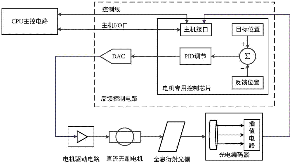
[0034] In order to make the minimum resolvable bandwidth of the spectroscopic unit of the spectrum analyzer reach 0.05nm, according to the grating equation λ=(2d / m)sinθ, the angular resolution requirement for the grating positioning device can be calculated. If a grating with a groove line density of 1000l / mm is used, at a wavelength of 1310nm, the rotation angle of the grating when it sweeps a spectral bandwidth of 1nm is about 660μrad. In order to display an optical signal with a narrow spectral width, there must be at least 10 data points within the minimum resolvable spectral width of the instrument of 0.05nm, so there are 200 data points within 1nm, that is, 660μrad corresponds to 200 data points, and it is calculated from this that the system The requirement for the angular resolution of the grating is about 3.3μrad, that is to say, at least 1904000 dat...


PUM


Abstract

The invention discloses a grating positioning device and method for a high-precision spectrum analyzer, comprising: a motor drive circuit, a DC brushless motor, a diffraction grating, a photoelectric encoder and a feedback control circuit connected in series in sequence, and the output end of the photoelectric encoder Connect the input end of the interpolation circuit; the CPU main control circuit is connected with the feedback control circuit; the rotor of the DC brushless motor is directly fixed on the rotating shaft of the diffraction grating; the beneficial effect of the present invention is that the DC brushless motor is selected to replace the stepping motor , to achieve direct drive and direct reading of the angular position of the grating, with the advantages of fast, robust, small size, no return difference, and insensitive to wear or environmental changes.

Description

technical field [0001] The invention relates to the technical field of grating positioning for spectrum analyzers, in particular to a high-precision grating positioning device and method for spectrum analyzers. Background technique [0002] At present, due to the advantages of large transmission capacity, high transmission rate, anti-electromagnetic interference, and strong confidentiality, optical fiber communication technology has been rapidly developed and widely used in various fields such as military, industry, agriculture, medical treatment, and scientific research. The grating rotating spectrum analyzer is the most common optical frequency domain measurement instrument in the optical fiber communication system, and its wavelength tuning is controlled by the angular position of the diffraction grating of the spectroscopic unit. The incident light beam is collimated by the collimating parabolic mirror and irradiated on the diffraction grating, and different lights diver...

Claims


Application Information

Patent Timeline
Patent Type & Authority Patents(China)
IPC IPC(8): G05D13/62
CPCG05D13/62
Inventor 侯喜报张志辉韩顺利
Owner THE 41ST INST OF CHINA ELECTRONICS TECH GRP
Why Eureka
Try Eureka