Interception and drainage pressure-reduction anti-floating system

A technology for decompression well pipes and underground structures, applied in protection devices, buildings, infrastructure engineering, etc., can solve problems such as hidden dangers left by the subsequent development of underground spaces, excessive pressure on drainage structures, and increased risk of silting, and achieve Optimize the effect of anti-floating, reduce water pressure, and facilitate construction

Active Publication Date: 2016-05-11
SOUTH CHINA UNIV OF TECH
View PDF7 Cites 14 Cited by
  • Summary
  • Abstract
  • Description
  • Claims
  • Application Information

AI Technical Summary

Problems solved by technology

Traditional anti-floating methods include setting uplift piles, uplift anchors, and increasing self-weight, etc. These methods have high construction costs and long construction periods, which increase sharply with the increase in depth and area of ​​underground structures, and even increase with the increase in groundwater level. Changes cannot be accurately predicted. A large number of uplift anchors and uplift piles are permanently left in the soil layer, which interferes with the original stratum environment and leaves hidden dangers for the subsequent development of underground space, which is contrary to the concept of green buildings.
[0003] Compared with traditional methods, drainage decompression and anti-floating methods have great advantages in terms of economy, construction period and environmental protection, but only emphasizing drainage is not enough. Uncontrolled drainage will cause serious environmental problems, and at the same time bring excessive damage to the drainage structure. The risk of silting increases and the reliability decreases. Therefore, while emphasizing drainage, it is also necessary to reduce the amount of seepage through water interception measures, that is, the interception, decompression and anti-floating system

Method used


Image

  • Interception and drainage pressure-reduction anti-floating system
  • Interception and drainage pressure-reduction anti-floating system
  • Interception and drainage pressure-reduction anti-floating system

Examples


Embodiment Construction

[0026] In order to enable those skilled in the art to better understand the technical solution of the present invention, the present invention will be further described in detail below in conjunction with the accompanying drawings. Obviously, the embodiments described below are only part of the embodiments of the present invention.

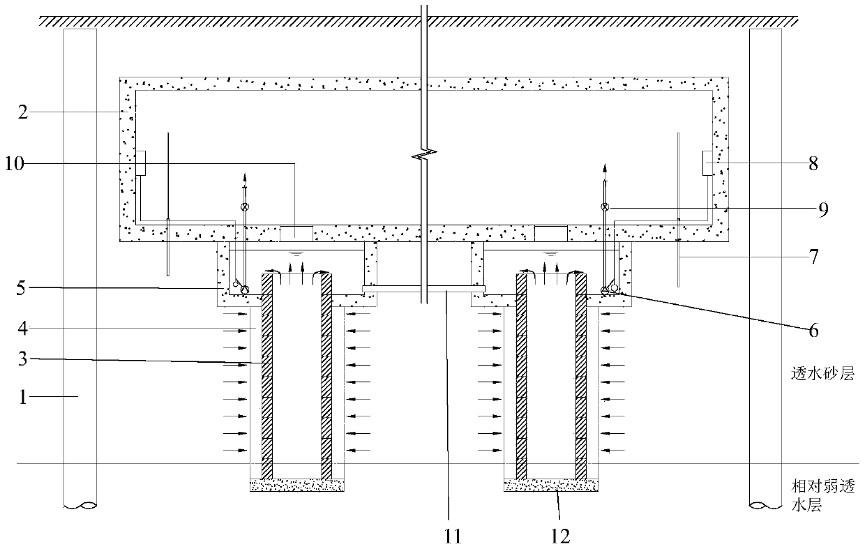
[0027] Such as figure 1 As shown, the present invention provides a kind of cut-off decompression anti-floating system, including water-stop curtain 1 arranged around the underground structure 2, several sumps 5 are arranged under the bottom plate of the underground structure 2, and the water-collecting The pit 5 is provided with a submersible pump 6 connected to the circuit of the submersible pump automatic control cabinet and a water level sensor switch. The bottom of the sump 5 is provided with a well hole extending downward, and a decompression well pipe is provided in the well hole. A reverse filter layer 4 with a thickness of not less than 30...


PUM


Abstract

The invention discloses an interception and drainage pressure-reduction anti-floating system which comprises a waterproof curtain arranged around an underground structure. A plurality of water collecting pits are formed below a bottom plate of the underground structure. Immersible pumps and water level induction switches are arranged in the water collecting pits. Well holes are formed in the bottoms of the water collecting pits. Pressure-reduction well pipes are arranged in the well holes. Anti-filtration layers are arranged around the pressure-reduction well pipes. The tops of the pressure-reduction well pipes are higher than openings of the well holes. The anti-filtration layers are located in the water collecting pits. The pressure-reduction well pipes are mainly formed by axially and vertically stacking a plurality of non-fine concrete well rings. The non-fine concrete well rings comprise upper annular ring beams, lower annular ring beams, stand columns and non-fine concrete wedge-shaped blocks. By means of cooperative work of the system, buoyant force on the bottom plate can be effectively reduced, the drainage amount can be controlled, the surrounding is protected against surface subsidence caused by the too large drainage amount, the number of uplift piles and the number of uplift anchor rods are greatly decreased, non-fine concrete blocks can be conveniently dismounted and replaced, and it is guaranteed that a pressure-reduction well has enough durability.

Description

technical field [0001] The invention belongs to the field of underground engineering anti-floating technology, and in particular relates to an anti-floating system for interception, decompression and anti-floating. Background technique [0002] At present, large and medium-sized cities across the country have successively entered the stage of large-scale development and utilization of underground space, and underground complexes with large scale and complete functions have emerged as the times require. These ultra-large underground structures have the characteristics of large buried depth and large area, but the superstructure has a small self-weight, and the problem of anti-floating is very prominent. Traditional anti-floating methods include setting uplift piles, uplift anchors, and increasing self-weight, etc. These methods have high construction costs and long construction periods, which increase sharply with the increase in depth and area of ​​underground structures, an...

Claims


Application Information

Patent Timeline
Patent Type & Authority Applications(China)
IPC IPC(8): E02D31/12E02D19/18E02D19/10
CPCE02D19/10E02D19/18E02D31/12E02D2600/00
Inventor 曹洪朱东风潘泓骆冠勇
Owner SOUTH CHINA UNIV OF TECH
Why Eureka
Try Eureka