High-pressure-resistant washing system with multiple mechanical seals

A mechanical seal and flushing system technology, applied in the direction of mechanical equipment, machines/engines, liquid fuel engines, etc., can solve problems such as centrifugal pumps not being able to withstand high pressure, centrifugal pumps not working properly, centrifugal pumps leaking, etc., to achieve pressure bearing The effect of increased force, small footprint, and low production cost

Active Publication Date: 2016-06-15
天津长瑞大通流体控制系统有限公司
View PDF4 Cites 3 Cited by
  • Summary
  • Abstract
  • Description
  • Claims
  • Application Information

AI Technical Summary

Problems solved by technology

[0017] The above-mentioned problems have always restricted the centrifugal pump from being able to withstand high pressure, because in the prior art, the mechanical seal is the weakest link of all components in the centrifugal pump. If the pressure bearing capacity of the mechanical seal is not improved, no matter how thick the pump casing is made, No matter how high the strength of other parts is, it will not help. Once the material pressure in the centrifugal pump exceeds the pressure bearing capacity of a single set of mechanical seals, the centrifugal pump will leak immediately. If the centrifugal pump leaks, it will not work normally, or even stop production.

Method used


Image

  • High-pressure-resistant washing system with multiple mechanical seals
  • High-pressure-resistant washing system with multiple mechanical seals
  • High-pressure-resistant washing system with multiple mechanical seals

Examples


Embodiment Construction

[0055] The high-pressure flushing system with multiple sets of mechanical seals of the present invention will be described in detail below with reference to the embodiments and the accompanying drawings.

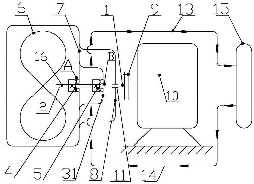
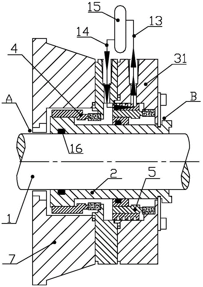
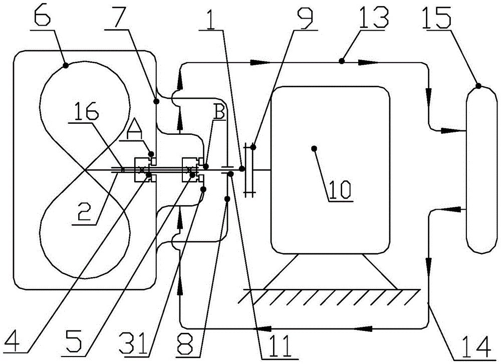
[0056] Such as Figure 5 , Figure 6 As shown, the high-pressure flushing system with multiple sets of mechanical seals of the present invention includes a centrifugal pump composed of a pump casing 7, an impeller 6 arranged in the pump casing 7, and a pump shaft 1 connected to the impeller 6 at one end. The other end of the pump shaft 1 extends out of the pump casing 7 through the high-pressure end mechanical seal 4 arranged on the shaft outlet hole of the pump casing 7, and the end is connected to the motor 10 for driving the impeller 6 to rotate through a coupling 9. The end of the pump shaft 1 connected to the shaft coupling 9 is positioned through the bearing 11 arranged on the bearing seat 8, and the outside of the pump shaft 1 is covered with a shaft sleeve 2, and th...


PUM


Abstract

The invention provides a high-pressure-resistant washing system with multiple mechanical seals. A centrifugal pump is composed of a pump shell, an impeller and a pump shaft. One end of the pump shaft stretches out of the pump shell through the high-pressure end mechanical seal and is connected with a motor through a coupler. The end, connected with the coupler, of the pump shaft is positioned through a bearing arranged on a bearing pedestal. The pump shaft is sleeved with a shaft sleeve which is fixedly connected with the pump shaft through a shaft sleeve sealing ring. The exterior, located between the pump shell and the bearing, of the shaft sleeve forms a first buffering liquid cavity,..., and an Nth buffering liquid cavity in the manner that a first sealing gland,..., and an Nth sealing gland are connected in a sealed manner end to end; each mechanical seal connected with the shaft sleeve in a sealed manner is arranged on the high-pressure side of the corresponding sealing gland; a liquid inlet of each sealing gland is connected with a liquid outlet of a pressure accumulator internally containing buffering liquid through a liquid inlet pipeline; a liquid outlet of each sealing gland is connected with a liquid inlet of the pressure accumulator through a liquid outlet pipeline; and the bottoms, close to the pump shell, of the sealing glands are connected with the pump shell in a sealed manner. By means of the high-pressure-resistant washing system with the multiple mechanical seals, the high-pressure-resistant capacity of an existing centrifugal pump can be substantially improved.

Description

technical field [0001] The invention relates to a shaft seal flushing system of a centrifugal pump. In particular, it relates to a high-pressure flushing system with multiple sets of mechanical seals that are connected in series to form a step-by-step pressure decrease with multiple sets of mechanical seals. Background technique [0002] In appendix D of the API682 standard for shaft seal systems of centrifugal pumps and rotor pumps, the pressure of the internal circulating fluid of the standard seal 52, 53 flushing scheme system is different, such as figure 1 and figure 2 Shown is the prior art of 52 flushing schemes, the liquid between two sets of mechanical seals facing back is non-pressurized and circulating buffer. in, [0003] figure 1 and figure 2 It is a prior art 2CW-CW container double-contact wet seal with buffer, and a schematic diagram of a buffer flushing system without pressure (connected to the atmosphere) and capable of circulating flow ( figure 1 ) ...

Claims


Application Information

Patent Timeline
IPC IPC(8): F04D29/70F04D29/08F04D29/42
CPCF04D29/08F04D29/42F04D29/70F04D29/708F04D29/086F04D29/426
Inventor 邢天宜邢宇
Owner 天津长瑞大通流体控制系统有限公司
Why Eureka
Try Eureka