Formwork-free prefabricated assembly type cavity plate

A prefabricated assembly, cavity board technology, applied in the direction of floor slabs, building components, buildings, etc., can solve problems affecting construction speed, vulnerable safety, hidden dangers, etc.

Inactive Publication Date: 2016-07-20
HUNAN BDF ENERGY SAVING TECH +2
View PDF14 Cites 6 Cited by
  • Summary
  • Abstract
  • Description
  • Claims
  • Application Information

AI Technical Summary

Problems solved by technology

[0007] The purpose of the present invention is to promote the process of housing industrialization, using a formwork-free prefabricated assembled cavity slab to improve the existing frame shear wall structure system; fully utilizing the advantages of factory industrialization, prefabricated and produced assembled cavity slabs, to solve The problems of construction, environmental protection, weight, cost, and work efficiency in the existing system; the overall force of the building structure is solved by pouring reinforced concrete on site, and the industrialized production of prefabricated floor slabs is organically combined with the reinforced concrete poured on site to achieve optimization. The existing frame shear wall structure system technology is used to transform and upgrade the existing prefabricated frame shear wall structure system; to solve the problems of the existing system, such as poor controllability of overall on-site pouring, strong technical implementation, and environmental pollution caused by on-site construction , heavy weight, high construction cost, slow progress of the project, exempting a large number of building formwork and steel supports, resulting in long formwork time and affecting the construction speed; the use of steel supports and its structural parts are vulnerable to safety hazards and difficult to form industrialized production.

Method used


Image

  • Formwork-free prefabricated assembly type cavity plate
  • Formwork-free prefabricated assembly type cavity plate
  • Formwork-free prefabricated assembly type cavity plate

Examples


Embodiment Construction

[0022] The invention will be further described below in conjunction with the accompanying drawings.

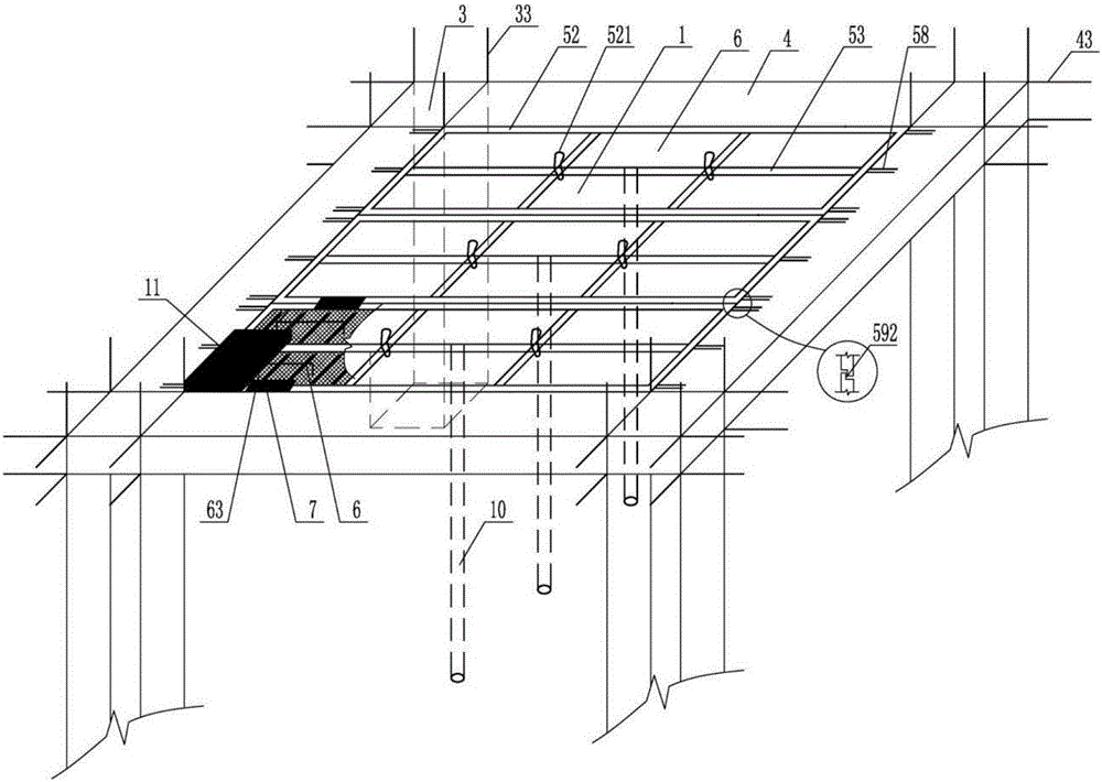
[0023] figure 1It is a plan view of a formwork-free prefabricated assembly cavity slab of the present invention. When the present invention is implemented, it will be a prefabricated assembly cavity floor 2 produced on the factory assembly line; The bottom mold system is transferred to the molding workshop and the rib steel bar and filling body workshop; the vertical formwork is installed on the bottom mold to form an open base formwork of the required specification and model, and the rib beam reinforcement and ribbed steel are placed in the open base formwork Net engraving, willow molds, pipes connecting ribs, etc.; then transfer the bottom form system with surrounding rails to the pouring workshop. The computer automatically mixes the proportions of cement, sand, and stone, and then sends it to the mixing station to add water and mix it into concrete. The fall is controlled...


PUM


Abstract

The invention provides a formwork-free prefabricated assembly type cavity plate which comprises reinforced concrete rib beams, a steel mesh concrete bottom flange plate and a prefabricated component made from a ribbed steel mesh carving plate, wherein the reinforced concrete rib beams include at least two reinforced concrete longitudinal rib beams and multiple reinforced concrete transverse rib beams; the two ends of the rebar of the reinforced concrete longitudinal rib beam are exposed; multiple annular rebars are arranged on the upper surface of the reinforced concrete rib beam; a ribbed steel mesh body is compounded in the steel mesh concrete bottom flange plate and produced from sheet steel by die cutting and compression moulding and used for producing the ribbed steel mesh carving plate; the ribbed steel mesh carving plate is composed of a carving mesh, a carving end mesh and a support object; and the ribbed steel mesh carving plate is exposed on the upper surface of the formwork-free prefabricated assembly type cavity plate. The assembly type cavity floor slab produced by the flow has the advantages of high integrity, reasonable structure, high quality standard, controlled processes and good self-insulation and sound insulation performance.

Description

technical field [0001] The invention relates to a housing industrialization system technology, in particular to a formwork-free prefabricated cavity panel technology. Background technique [0002] In the 1980s, the production of concrete prefabricated components in my country was in a stage of great development. In the process of housing construction, the country adopted hollow prefabricated slab structures, large slab structures, cast-in-place concrete structures, cast-in-place concrete hollow floor slab structures, and cast-in-place frame shear forces. Wall structure, etc. With the process of housing industrialization, steel-concrete composite structure and steel-concrete composite cavity floor structure system have been developed rapidly. [0003] For example, the ZL98231113.3 concrete thin-walled cylindrical member declared by the applicant is made into a sealed cylindrical filling body, which provides a tubular hollow filling body for the realization of the cast-in-place...

Claims


Application Information

Patent Timeline
Patent Type & Authority Applications(China)
IPC IPC(8): E04B5/36
Inventor 王本淼王海崴韩爱兴尚仁杰马锋
Owner HUNAN BDF ENERGY SAVING TECH
Why Eureka
Try Eureka