
Wind generating device and method

A technology for generating wind and electric potential, applied in the direction of electrical components, etc., can solve problems such as inappropriate

Active Publication Date: 2017-07-21
TAIYI ENVIRONMENT TECH SHANGHAI CO LTD
View PDF1 Cites 0 Cited by
  • Summary
  • Abstract
  • Description
  • Claims
  • Application Information

AI Technical Summary

Problems solved by technology

Therefore, this device is not suitable for making artificial wind in wind engineering.

Method used


Image

  • Wind generating device and method
  • Wind generating device and method
  • Wind generating device and method

Examples


Embodiment 1

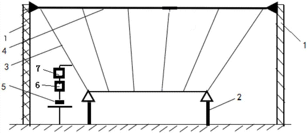
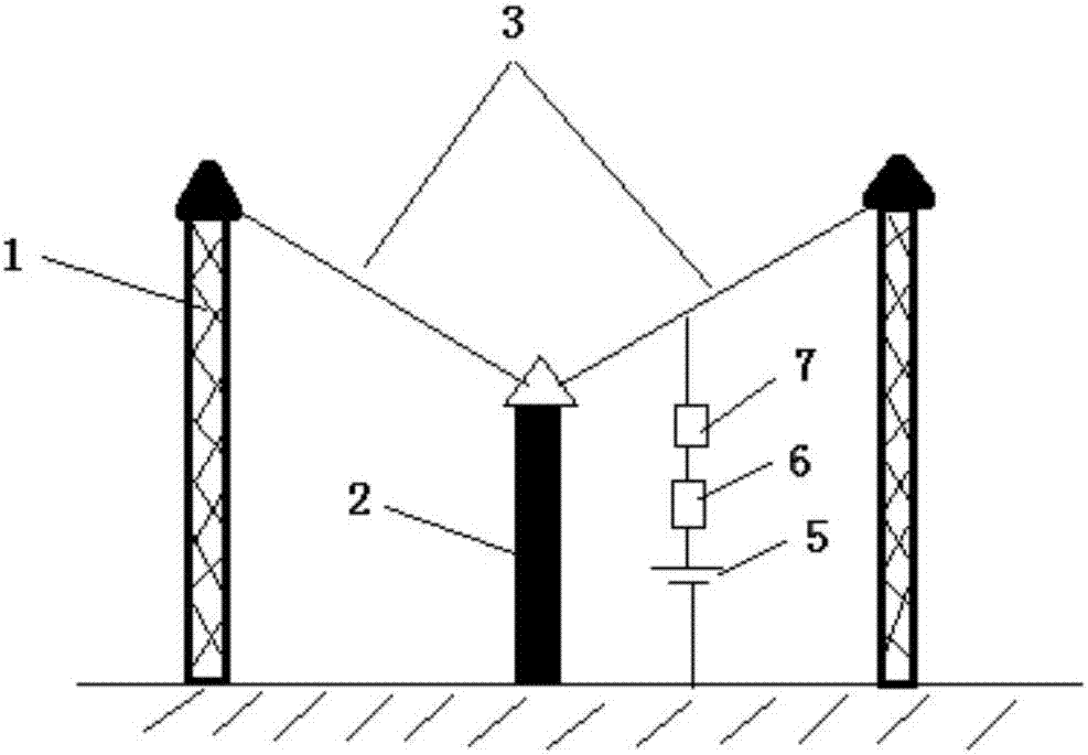
[0028] Such as Figure 1-2 As shown, a wind generating device includes potential output units A and B, each potential output unit includes two high cable support units and a low cable support unit, and the high cable support unit consists of two high supports 1 and erected The cable 4 between two high brackets 1 is composed; the low cable bracket unit is composed of two low brackets 2 and the cable 4 erected between the two low brackets; the two high cable bracket units are respectively located in the low cable bracket On both sides of the unit; between the cable 4 on the high cable support unit and the cable 4 on the low cable support unit, there are 6 launching wires 3 connected, and the total length of the launching wires 3 is 1000 meters.

[0029] The distance between the high supports is 180 meters, the height of the high supports H 0 is 35 meters, the distance D between adjacent transmitting wires 3 0 is 36 meters; the distance between two low supports is 21 meters, an...


PUM


Abstract

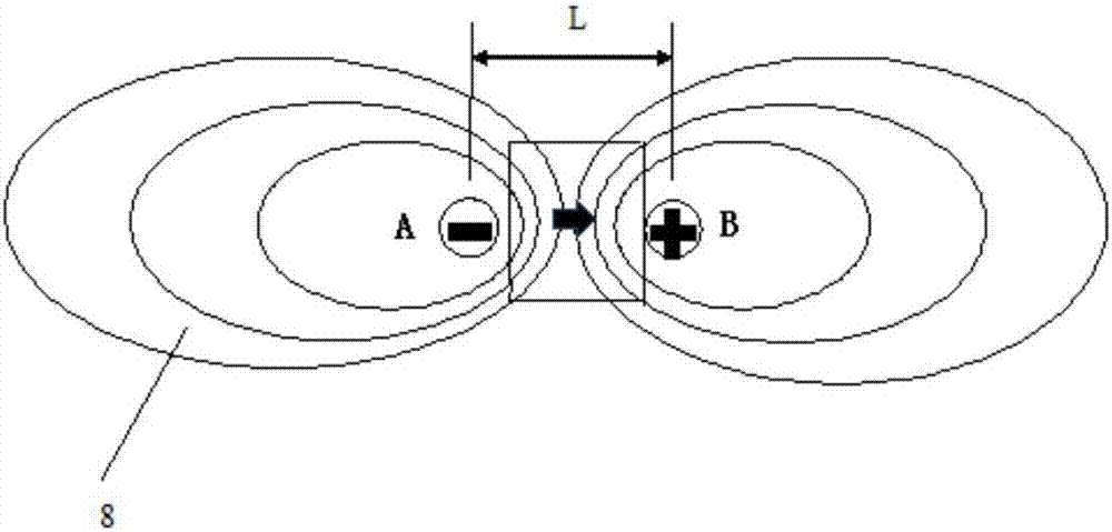
The invention discloses a wind creation device. The wind creation device comprises more than two electric potential output units, wherein different electric potential output units are arranged at a distance of 3,000-100,000 meters and are in potentials with opposite polarities. The device is mainly used in wind engineering, and is used for increasing precipitation and preventing forest fire.

Description

technical field [0001] The invention belongs to the field of air ionization, and in particular relates to a wind generating device capable of promoting air flow. Background technique [0002] The dependence of atmospheric flow and atmospheric electrical state, as well as the possibility of artificially influencing processes by changing the concentration and polarity of ions in the air over large regions, has been theoretically demonstrated in published scientific studies. In the last decade, a variety of ground-based air ionizers have been developed to use electrons and ions to exert an influence on the atmosphere. [0003] The "wind" formed by the general air flow is usually achieved by the motor rotating the fan blades. All types of aeroengines belong to this type of wind generating device. These devices utilize the internal energy of combustible substances, and the energy consumption of wind-making is equal to or exceeds the flow energy of the wind-making. The power of ...

Claims


Application Information

Patent Timeline
Patent Type & Authority Patents(China)
IPC IPC(8): H01T23/00
CPCH01T23/00
Inventor 周晓春
Owner TAIYI ENVIRONMENT TECH SHANGHAI CO LTD
Learn More