Carrying device

A technology of handling device and handling mechanism, which is applied in the directions of storage device, transportation and packaging, can solve the problems of complex overall structure, high manufacturing cost, and excessive weight of handling device, and achieves simplification of overall structure, weight reduction and manufacturing. cost effect

Inactive Publication Date: 2016-08-10
致茂电子(苏州)有限公司
View PDF5 Cites 0 Cited by
  • Summary
  • Abstract
  • Description
  • Claims
  • Application Information

AI Technical Summary

Problems solved by technology

This makes the overall structure of the handling device too complicated, and the weight of the

Method used


Image

  • Carrying device
  • Carrying device
  • Carrying device

Examples


Embodiment Construction

[0048] The detailed features and advantages of the present invention are described in detail below in the embodiments, the content of which is sufficient for any person familiar with the relevant art to understand the technical content of the present invention and implement it accordingly, and according to the contents disclosed in this specification, claims and accompanying drawings, The related objects and advantages of the present invention can be easily understood by anyone skilled in the relevant art. The following examples further illustrate the concept of the present invention in detail, but do not limit the scope of the present invention in any way.

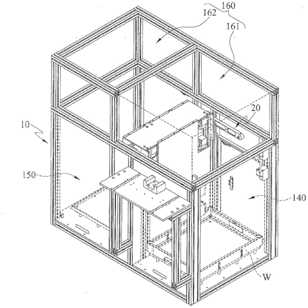
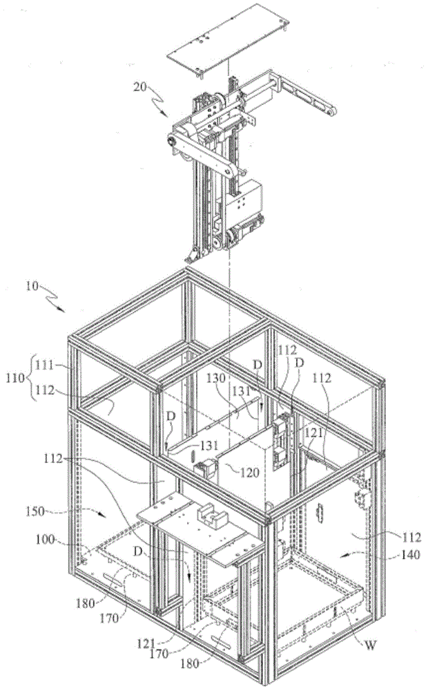
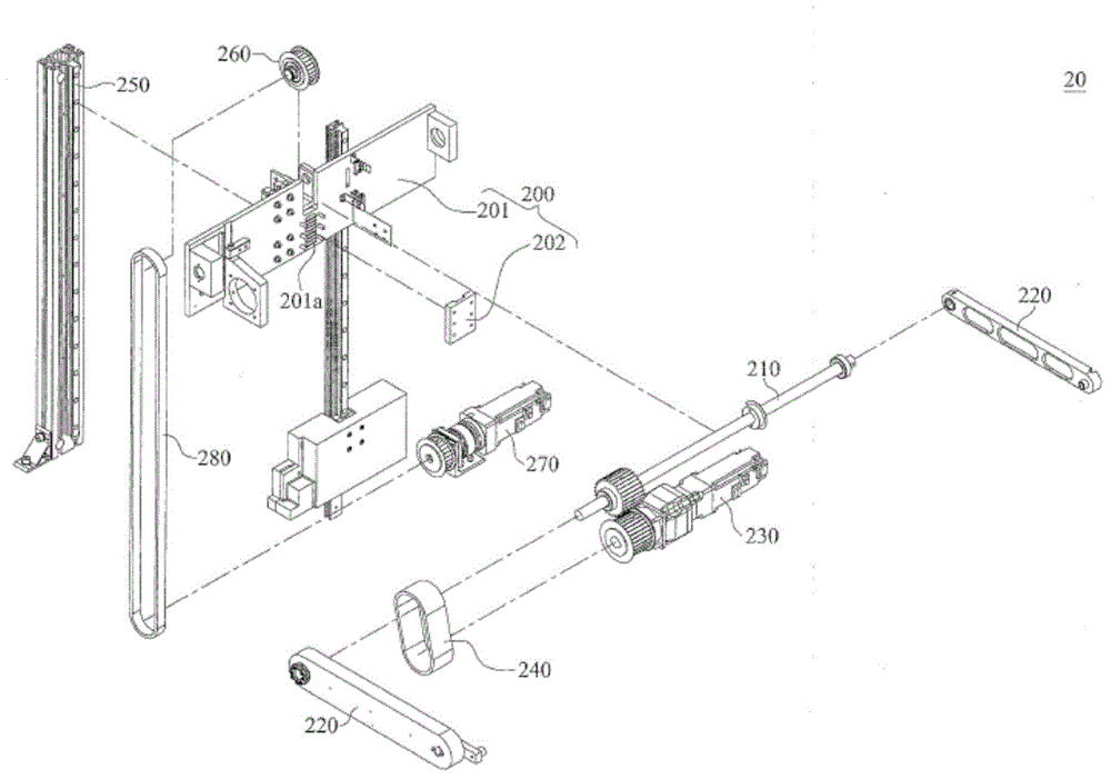
[0049] Please also refer to figure 1 , figure 2 with image 3 . figure 1 It is a three-dimensional schematic diagram of a conveying device according to an embodiment of the present invention. figure 2 It is an exploded schematic diagram of a conveying device according to an embodiment of the present invention. ima...


PUM


Abstract

The invention discloses a CNC automated processing system and method. The device comprises a material box, multiple CNC machines, a manipulator and a locating device. Multiple workpieces to be machined are arranged in the material box side by side. A machining region is enclosed by the multiple CNC machines and the material box. All the CNC machines perform machining operation on the workpieces in different procedures and are internally provided with machining fixtures. The manipulator is arranged in the machining region and the end part of the manipulator is provided with a clamp used for clamping the workpieces. A controller is arranged in the manipulator and in signal connection with the all the CNC machines, the machining fixtures and the clamp, which is used for controlling on-off of the all the CNC machines, switches of the machining fixtures and controlling the clamp to take and pick the workpieces. The locating device is arranged in the machining region and used for locating the workpieces. The method utilizes the device to transfer the workpieces in different procedures so that time and labor can be saved, and errors caused by frequent operation of an operator and industrial injury danger are avoided.

Description

technical field [0001] The invention discloses a conveying device, in particular a conveying device with a rotating power source and a lifting power source. Background technique [0002] Today's industrial production mostly uses handling devices to move work pieces to save manpower and improve production efficiency. [0003] Generally speaking, the conveying device includes multiple transmission mechanisms and multiple power sources (such as motors or cylinders) corresponding to these transmission mechanisms. In order to use the handling device to pick up the items and transport the items between two storage spaces at different locations, the traditional handling device requires at least two power sources so that the handling device can pick up or unload the items, and another power is required. The source enables the handling device to transport items between two storage spaces at different locations. This makes the overall structure of the conveying device too complicate...

Claims


Application Information

Patent Timeline
IPC IPC(8): B65G1/04
Inventor 张添登温镇州
Owner 致茂电子(苏州)有限公司
Why Eureka
Try Eureka