A kind of preparation device and method of composite blow bar

A composite material plate and preparation device technology, which is applied in the field of blow bar preparation device, can solve the problems of ceramic fragility and falling off, uneven distribution of ceramic particles, and poor combination of ceramic and matrix, so as to achieve no shrinkage defects, enhanced durability Abrasive, smooth effect

Inactive Publication Date: 2017-11-28
BEIJING JIAOTONG UNIV
View PDF6 Cites 1 Cited by
  • Summary
  • Abstract
  • Description
  • Claims
  • Application Information

AI Technical Summary

Problems solved by technology

It solves the problems of uneven distribution of ceramic particles in the matrix, weak combination of ceramics and matrix, and fragile ceramics falling off during use in the existing composite material blow bar preparation technology

Method used


Image

  • A kind of preparation device and method of composite blow bar
  • A kind of preparation device and method of composite blow bar

Examples


Embodiment 1

[0047] Example 1 - high manganese steel + corundum blow bar

[0048] This embodiment discloses a method for preparing a corundum particle-reinforced high manganese steel composite blow bar. The basic principles and required devices of the method are as described above.

[0049] Its concrete preparation process comprises steps:

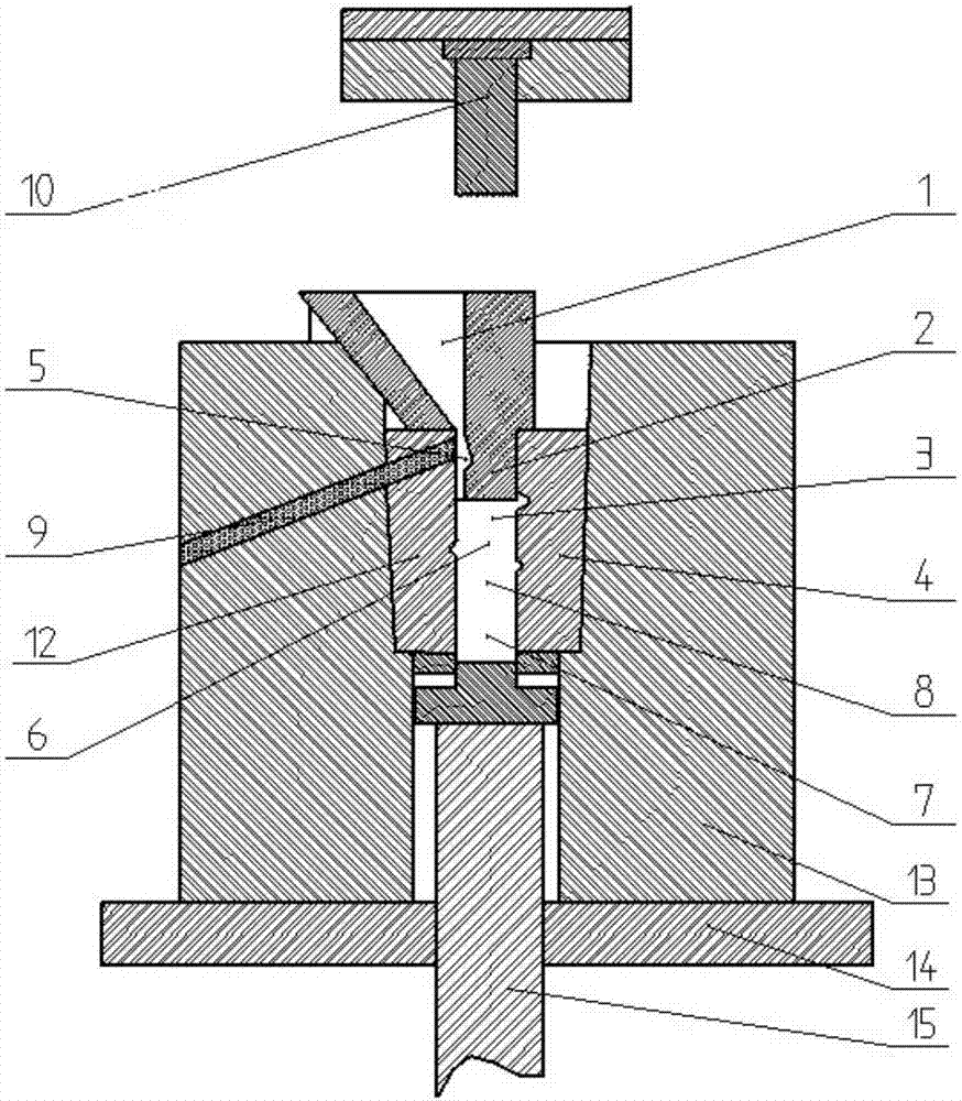
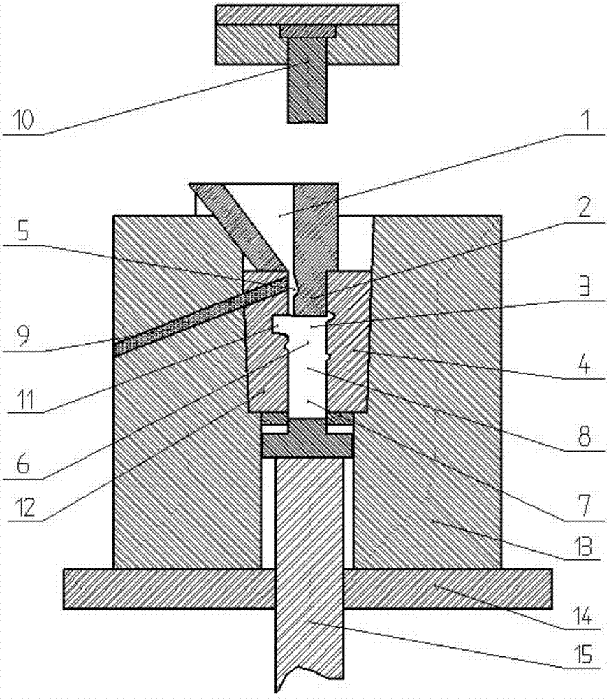
[0050] S1 Preheating: Preheat the blow bar cavity 3 and the ceramic particle cavity 9 to 200°C, and preheat the corundum particles to 1000°C;

[0051] S2 filling ceramic particles: adding preheated corundum particles into the ceramic particle cavity 9, the average particle size of the corundum particles is 2mm;

[0052] S3 Place the sprue cup: place the sprue cup 1 directly above the blow bar cavity 3, the left boundary of the outlet is flush with the left wall of the blow bar cavity 3, and the baffle plate 2 on the right side of the sprue cup 1 Extend into the sprue cavity 5;

[0053] S4 Mixing with flow: While pouring high manganese molten steel w...

Embodiment 2

[0057] Example 2 - high chromium cast iron + zirconia blow bar

[0058] This example discloses a method for preparing a zirconia particle reinforced high-chromium cast iron composite blow bar. The basic principles and required devices of the method are as described above.

[0059] Its specific preparation process includes:

[0060] S1 Preheating: preheat blow bar cavity 3 and ceramic particle cavity 9 to 250°C, and preheat zirconia particles to 1200°C;

[0061] S2 filling ceramic particles: adding preheated zirconia particles into the ceramic particle chamber 9, the average particle size of the zirconia particles is 2mm;

[0062] S3 Place the sprue cup: place the sprue cup 1 directly above the blow bar cavity 3, the left boundary of the outlet is flush with the left wall of the blow bar cavity 3, and the baffle plate 2 on the right side of the sprue cup 1 Extend into the sprue cavity 5;

[0063] S4 Mixing with the flow: while pouring the high chromium cast iron liquid with ...

Embodiment 3

[0067] Example 3 - high chromium cast iron + ZTA blow bar

[0068] This embodiment discloses a method for preparing a ZTA particle reinforced high-chromium cast iron composite blow bar. The basic principle and required devices of the method are as described above.

[0069] Its specific preparation process includes:

[0070] S1 Preheating: Preheat the blow bar cavity 3 and the ceramic particle cavity 9 to 150°C, and preheat the ZTA particles to 800°C;

[0071] S2 Filling with ceramic particles: adding preheated ZTA particles into the ceramic particle chamber 9, the average particle size of the ZTA particles is 2 mm;

[0072] S3 Place the sprue cup: place the sprue cup 1 directly above the blow bar cavity 3, the left boundary of the outlet is flush with the left wall of the blow bar cavity 3, and the baffle plate on the right side of the sprue cup 1 extends into the sprue cavity 5;

[0073] S4 Mixing with flow: While pouring the high chromium cast iron liquid with a superheat...


PUM

PropertyMeasurementUnit
heightaaaaaaaaaa
particle sizeaaaaaaaaaa

Abstract

The invention relates to a preparation device and method for a composite plate hammer. The preparation device comprises a sprue cup, a plate hammer mold cavity, a left half mold, a right half mold, a sprue cavity, a ceramic particle cavity, a pressing head, a mold locking seat, a mold bottom plate and a lower jacking block. The preparation method comprises the following steps that S1, the plate hammer mold cavity and the ceramic particle cavity are preheated to 150-250 DEG C, and ceramic particles are preheated to 800-1200 DEG C; S2, the preheated ceramic particles are added into the ceramic particle cavity to the set quantity; S3, the sprue cup is placed; S4, mixing is conducted along with flowing; S5, liquid forging compounding is conducted, specifically, within the time of 5-15 seconds after pouring of plate hammer molten metal is stopped, a ceramic particle-metal mixture is pressurized directly by the pressing head until all the mixture is solidified; and S6, part out-taking and heat treatment are conducted, specifically, the left half mold and the right half mold are opened, the composite plate hammer is taken out and put into a slow cooling furnace to be cooled to 400 DEG C or below, reheating, quenching and tempering heat treatment are conducted, and the composite plate hammer is obtained.

Description

technical field [0001] The invention relates to a preparation device and method of a composite material blow bar, in particular to a preparation device and a preparation method of a blow bar, one of the main wearing parts of an impact crusher. Background technique [0002] The particles used in the preparation process of composite blow bars are millimeter-scale particles. The existing preparation technology mainly includes: stirring casting method, casting infiltration method, lost foam method and prefabricated body method. All of the above methods can realize the composite between ceramic particles and metal matrix, but none of them can completely solve the problems of uneven distribution of particles in metal matrix, poor interface bonding between ceramic particles and metal matrix, and particle peeling during use. [0003] A high-chromium cast iron blow bar structure invented by Li Lailong (application number: 201320352589.2) and an ultra-high manganese inlaid cast blow b...

Claims


Application Information

Patent Timeline
Patent Type & Authority Patents(China)
IPC IPC(8): B22D17/22B22D27/11C21D1/18
CPCB22D17/22B22D27/11C21D1/18
Inventor 邢书明董琦邱博
Owner BEIJING JIAOTONG UNIV
Why Eureka
Try Eureka