An underground nuclear power plant cooling shaft

A technology for nuclear power plants and shafts, applied in the field of nuclear power, can solve the problems of wasting land resources in the site area of ​​nuclear power plants, covering a large area of ​​natural ventilation cooling towers, increasing construction difficulties and engineering costs, etc. The effect of saving engineering costs

Active Publication Date: 2017-11-28
CHANGJIANG SURVEY PLANNING DESIGN & RES
View PDF7 Cites 0 Cited by
  • Summary
  • Abstract
  • Description
  • Claims
  • Application Information

AI Technical Summary

Problems solved by technology

In terms of wind resistance and material savings, natural draft cooling towers are usually designed as hyperboloids, which increases construction difficulties and engineering costs
At the same time, natural draft cooling towers occupy a large area, especially when multi-reactors are arranged, which greatly wastes the land resources in the site area of ​​the nuclear power plant. Three reactors can be arranged on the ground, which brings huge economic benefits
In addition, the existing cooling tower adopts water-sprinkling packing technology, hot water flows through the water-sprinkling packing to form a liquid film to increase the heat exchange with the air. This technology needs to raise the circulating water above the arrangement height of the water-sprinkling packing, Due to the huge amount of cooling water circulation in nuclear power plants, the cost of upgrading the circulating water alone amounts to tens of millions of yuan each year

Method used


Image

  • An underground nuclear power plant cooling shaft
  • An underground nuclear power plant cooling shaft
  • An underground nuclear power plant cooling shaft

Examples


Embodiment Construction

[0019] The present invention will be described in further detail below in conjunction with the accompanying drawings and embodiments, but these embodiments should not be construed as limiting the present invention.

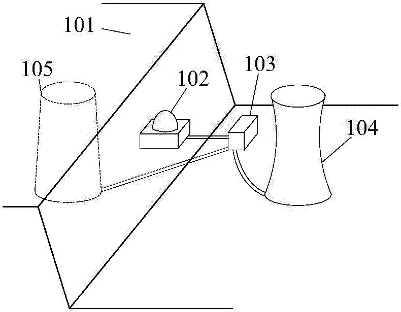
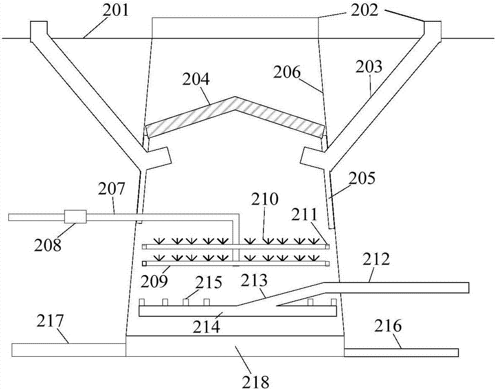
[0020] An underground nuclear power plant cooling shaft 105 of the present invention such as Figure 1 ~ Figure 3 As shown, it includes a frustum-shaped vertical shaft body 206 with an upper opening below the mountain ground 201. A sump 218 is provided at the bottom of the shaft body 206. The sump 218 is provided with a cooling water outlet pipe 217 and a sewage pipe 216. Below the inner cavity of the shaft body 206 There is an air supply system for conveying cold air.

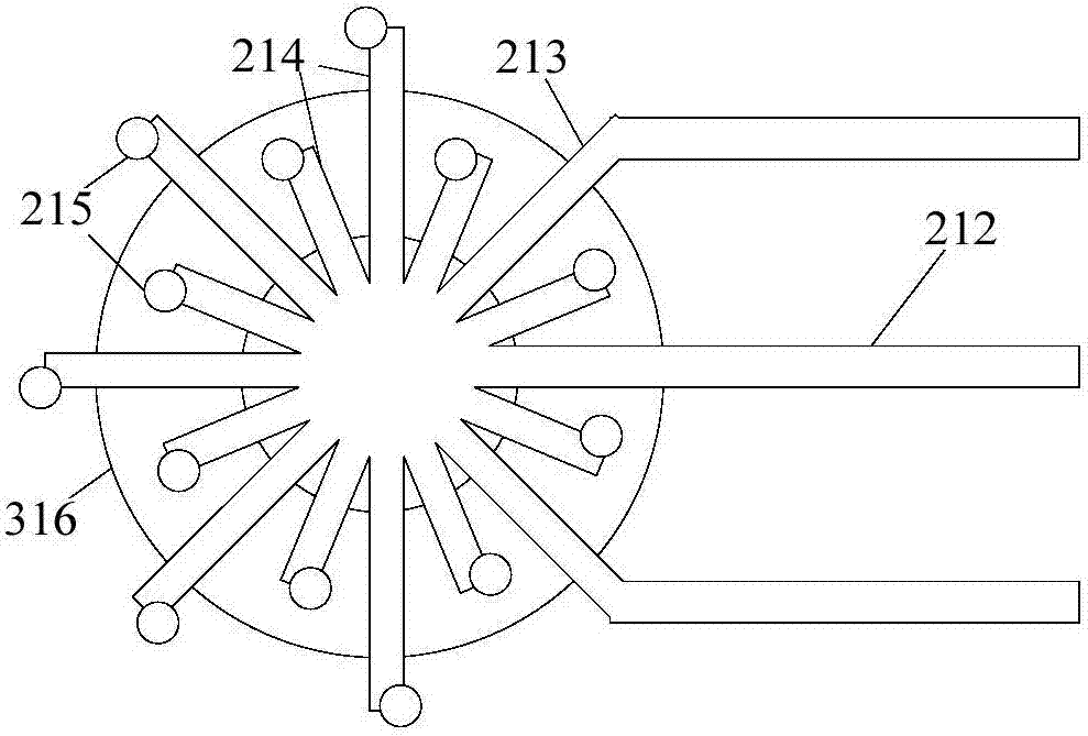
[0021] The air supply system includes an air inlet main pipe 212 , an air inlet distribution pipe 213 and several air inlet branch pipes 214 . One end of the air inlet dry pipe 212 communicates with the cold air source, and the other end communicates with the air inlet distribution pipe 213, and ...


PUM


Abstract

The invention discloses a cooling shaft of an underground nuclear power plant, which comprises a frustum-shaped vertical shaft body located in a mountain body with an upper opening. There is an air supply system for conveying cold air. Above the air supply system is a hot water distribution system connected to the condenser of the steam turbine generator. The hot water distribution system sprays the input hot water. In the middle of the inner cavity of the shaft body, there is a The cooling and ventilation corridor communicated with the outside of the ground surface, and the upper part of the inner cavity of the shaft body is provided with a demister. The invention uses the vertical shaft structure to replace the cooling tower structure, and through the principle of spray cooling, the hot water entering the cooling shaft forms atomized particles, which enhances the process of hot water evaporation and heat absorption, and forms a spiral whirlwind in the cooling shaft through the air supply system, strengthening heat exchange. At the same time, the setting of water spray filler is discarded, and the structure of the cooling shaft is greatly reduced, which effectively reduces the construction and operation costs.

Description

technical field [0001] The invention relates to nuclear power technology, in particular to an underground nuclear power plant cooling shaft. Background technique [0002] Nuclear power generation is to convert nuclear energy into internal energy of water vapor, and then drive a steam turbine to generate electricity through steam. In order to improve the efficiency of power generation, nearly two-thirds of the energy will be dissipated to the environment in the form of exhaust steam cooling during the process of steam driving the steam turbine to generate electricity. In order to reduce the impact of thermal pollution on the environment, the layout of underground nuclear power plants is as follows: figure 1 As shown, the nuclear island 102 is arranged inside the mountain 101 , and the steam turbine plant 103 is arranged on the ground platform not far from the nuclear island 102 . The nuclear island 102 uses the rock mass as a physical barrier, and its safety is higher. The...

Claims


Application Information

Patent Timeline
Patent Type & Authority Patents(China)
IPC IPC(8): F28C3/08G21D1/02
CPCF28C3/08G21D1/02Y02E30/00
Inventor 赵鑫刘海波张涛喻飞杨家胜金乾张鹏桂胜强袁博陈玉梅
Owner CHANGJIANG SURVEY PLANNING DESIGN & RES
Why Eureka
Try Eureka