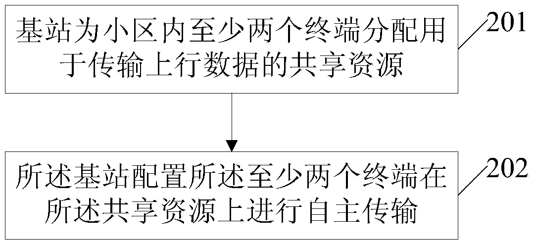
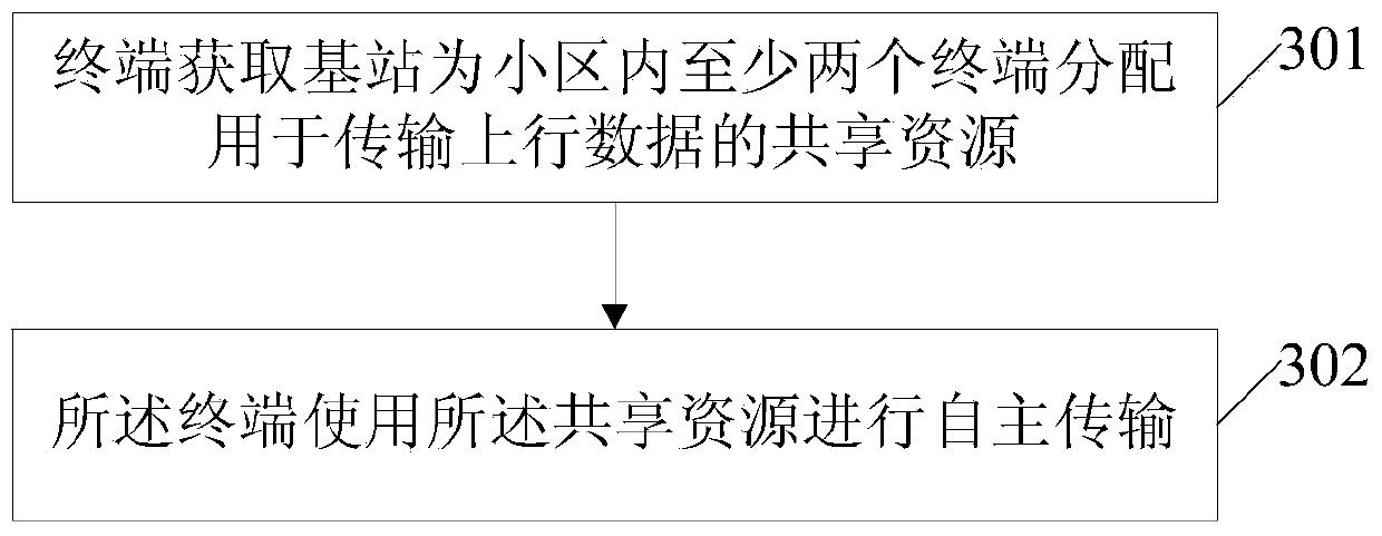
A transmission control method and device for uplink data
A technology for transmission control and data, applied in the field of communication, can solve the problems of difficult to ensure ultra-low delay transmission characteristics, complicated steps, etc., to meet the needs of fast transmission of uplink data, meet communication requirements, and improve the effect of large delay
- Summary
- Abstract
- Description
- Claims
- Application Information
AI Technical Summary
Problems solved by technology
Method used
Image
Examples
Embodiment 1
[0093] In this embodiment, the method provided by the present invention is described in detail for uplink data information transmission.
[0094] The base station allocates shared resources for transmitting uplink data information to a group of terminals in the cell that require low-latency transmission, and uses G-RNTI scrambled control channel scheduling group information for allocation. The allocated shared resources account for 30% of the total resources and are located at a position with a lower number in the frequency domain in the system bandwidth. At this time, the shared resources include temporary resources, and the temporary resources account for 50% of the shared resources.
[0095] After the base station allocates shared resources, terminals with low-latency transmission requirements perform autonomous transmission and send uplink data in the shared resource area. Terminals 1-10 all use different frequency domain resource units to send uplink data in subframe n, ac...
Embodiment 2
[0099] In this embodiment, the method provided by the present invention is described in detail for uplink data information transmission.
[0100] The base station allocates shared resources for transmitting uplink data information to all terminals in the cell that require low-latency transmission, and uses SI-RNTI scrambled control channel scheduling system information for allocation. The allocated shared resource accounts for 30% of the total resource and is located at a position with a lower frequency domain position number in the system bandwidth.
[0101]After the base station allocates shared resources, terminals with low-latency transmission requirements perform autonomous transmission and send uplink data in the shared resource area, and some terminals of terminals 1-100 use different frequency domain resource units to send uplink data in subframe n, according to Select 1, 2, 4, and 8 PRB for the respective data packet sizes. The base station receives and detects 80% of...
Embodiment 3
[0106] In this embodiment, the method provided by the present invention is described in detail for uplink data information transmission.
[0107] The base station allocates shared resources for transmitting uplink data information to all terminals in the cell that require low-latency transmission, and uses SI-RNTI scrambled control channel scheduling system information for allocation. The allocated shared resource accounts for 40% of the total resource and is located at a position with a lower frequency domain position number in the system bandwidth.
[0108] After the base station allocates shared resources, terminals with low-latency transmission requirements perform autonomous transmission and send uplink data in the shared resource area, and some terminals of terminals 1-100 use different frequency domain resource units to send uplink data in subframe n, according to Select 1, 2, 4, and 8 PRB for the respective data packet sizes. The base station receives and detects 80% o...
PUM
 Abstract
Description
Claims
Application Information
 - R&D
- Intellectual Property
- Life Sciences
- Materials
- Tech Scout
- Unparalleled Data Quality
- Higher Quality Content
- 60% Fewer Hallucinations
Browse by: Latest US Patents, China's latest patents, Technical Efficacy Thesaurus, Application Domain, Technology Topic, Popular Technical Reports.
© 2025 PatSnap. All rights reserved.Legal|Privacy policy|Modern Slavery Act Transparency Statement|Sitemap|About US| Contact US: help@patsnap.com


