A high-frequency response and large working distance self-collimation device and method

A working distance and self-collimation technology, which is applied in the direction of measuring devices, optical devices, instruments, etc., can solve the problems that the reflected beam deviates from the entrance pupil, the range cannot be too large, and the self-collimation and micro-angle measurement cannot be realized, achieving The effect of increasing the working distance, simple structure of the device, and increasing the working range of self-collimation

Active Publication Date: 2018-11-06
HARBIN INST OF TECH
View PDF3 Cites 0 Cited by
  • Summary
  • Abstract
  • Description
  • Claims
  • Application Information

AI Technical Summary

Problems solved by technology

[0008] First, the range of the angle between the normal of the mirror surface of the measured object 5 and the optical axis of the laser autocollimator should not be too large, otherwise the reflected beam will deviate from the entrance pupil of the laser autocollimator optical system, resulting in failure to achieve self-collimation Straight and micro angle measurement;
[0009] Second, the distance between the mirror surface of the measured object 5 and the entrance pupil of the laser autocollimator should not be too far away, otherwise as long as the reflected optical axis deviates from the optical axis of the autocollimator by a small angle, the reflected beam will deviate from the optical system of the laser autocollimator The entrance pupil, which leads to the inability to achieve self-collimation and micro-angle measurement
[0010] The above two problems limit the use of traditional autocollimation instruments to small angles and small working distances.

Method used


Image

  • A high-frequency response and large working distance self-collimation device and method
  • A high-frequency response and large working distance self-collimation device and method
  • A high-frequency response and large working distance self-collimation device and method

Examples


specific Embodiment 1

[0073] This embodiment is an embodiment of an autocollimation device with high frequency response and large working distance.

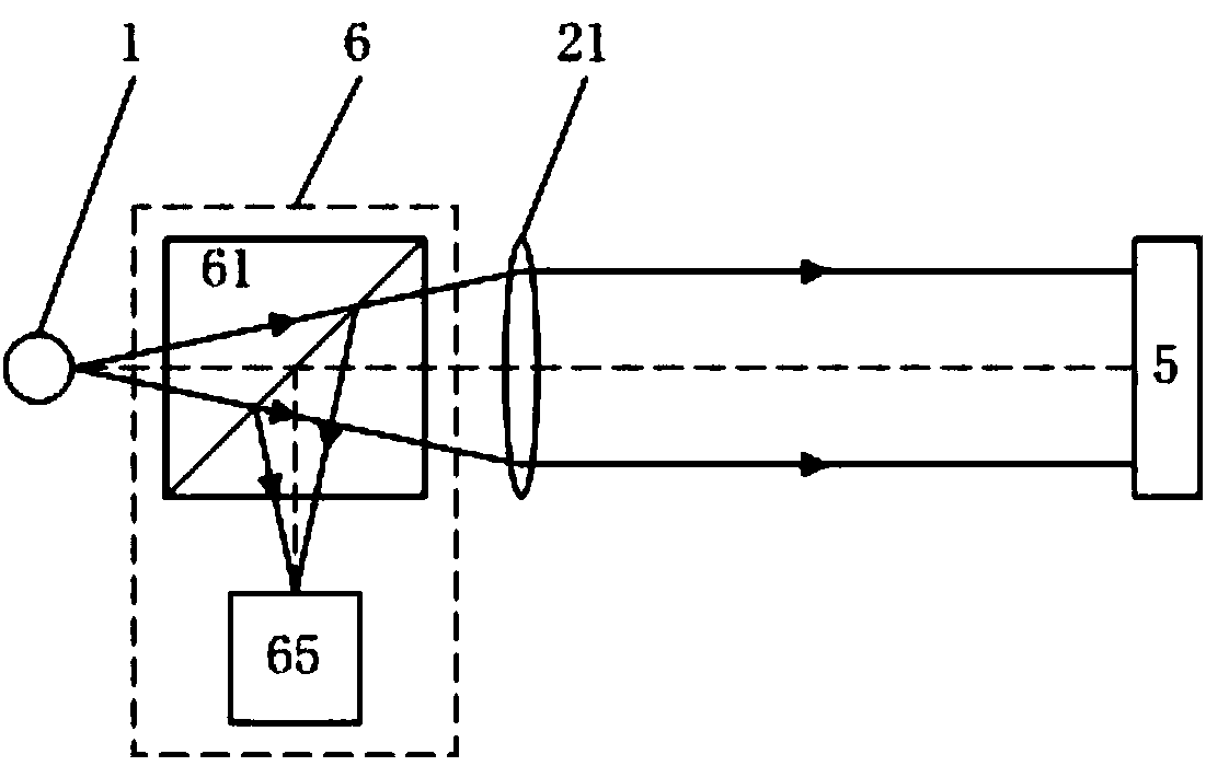
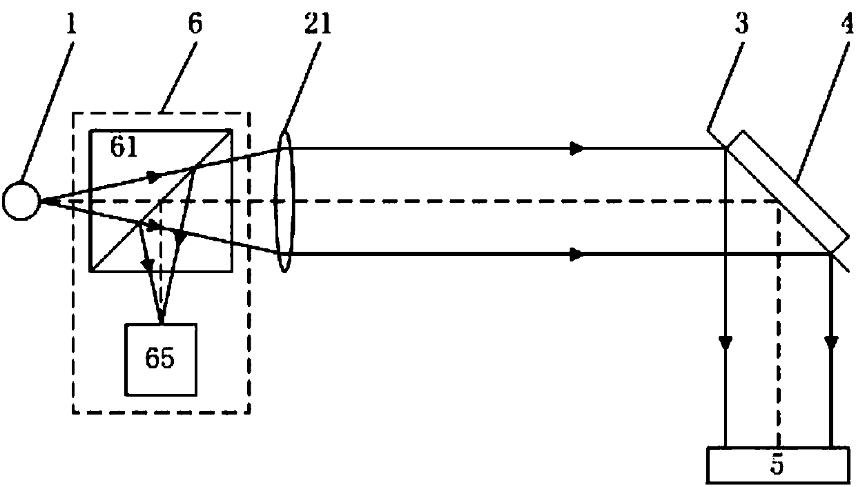
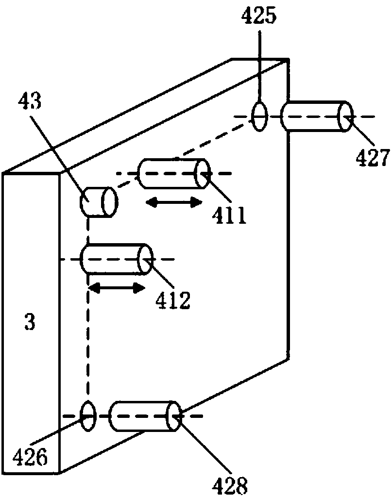
[0074] The structure diagram of the self-collimation device with high frequency response and large working distance in this embodiment is as follows figure 2 shown. The self-collimation device includes a light source 1, a transmissive collimator mirror 21, a reflector 3, and a feedback imaging system 6. The reflector 3 is provided with an angle adjustment measuring device 4; After the straight mirror 21 is collimated into a parallel light beam, it is reflected by the reflector 3 and incident on the surface of the measured object 5; the light beam reflected from the surface of the measured object 5 is then reflected by the reflective mirror 3 and collected by the feedback imaging system 6 imaging;

[0075] The feedback imaging system 6 is arranged between the light source 1 and the transmissive collimator 21, including a first feedback beamsplitter ...

specific Embodiment 2

[0078] This embodiment is an embodiment of an autocollimation device with high frequency response and large working distance.

[0079] The structure diagram of the self-collimation device with high frequency response and large working distance in this embodiment is as follows Figure 5 shown. On the basis of the specific embodiment 1, the high-frequency response and large working distance self-collimation device of this embodiment is also provided with a wavefront detection system 7 and a wavefront compensation system 8;

[0080] The wavefront detection system 7 includes a wavefront detection spectroscope 71 and an air disturbance wavefront detector 72; the wavefront detection spectroscope 71 is arranged between the reflector 3 and the measured object 5, and the air disturbance wavefront detector 72 is arranged on the reflected optical path of the wavefront detection spectroscope 71, and the mirror deformation wavefront detector 73 is arranged on the secondary reflected optic...

specific Embodiment 3

[0082] This embodiment is an embodiment of an autocollimation device with high frequency response and large working distance.

[0083] The structure diagram of the self-collimation device with high frequency response and large working distance in this embodiment is as follows Image 6 shown. On the basis of the specific embodiment 1, the high-frequency response and large working distance self-collimation device of this embodiment is also provided with a wavefront detection system 7 and a wavefront compensation system 8;

[0084] The wavefront detection system 7 includes a wavefront detection beamsplitter 71 and a mirror deformation wavefront detector 73; the wavefront detection beamsplitter 71 is arranged between the mirror 3 and the measured object 5, and the air disturbance wavefront detection The device 72 is arranged on the reflected optical path of the wavefront detection spectroscope 71, and the mirror deformation wavefront detector 73 is arranged on the secondary refle...


PUM


Abstract

The invention relates to a high-frequency-response long-working-distance auto-collimation device and method, and belongs to the fields of precise measurement technology and optical engineering. The device is composed of a light source, a collimating mirror, a reflector and a feedback imaging system. According to the method, the reflector is adjusted so that a reflection light beam returns to the center of an image plane of the feedback imaging system, and an angle deflection measuring device of the reflector is used to obtain angle change of the surface of a tested object. According to the invention, the reflector is added to a traditional auto-collimation angle measuring system, the problem that reflection light of the tested object is deviated the measuring system and further measurement cannot be carried out can be solved, and the auto-collimation work range is increased under the same work distance, or the working distance is increased under the same work range; concrete designs of the collimating mirror, the feedback imaging system, the reflector and the like enable the auto-collimating device to be small, portable and high in measuring precision; the measuring precision is high under low sampling frequency; and the measurement speed is very high.

Description

technical field [0001] The invention belongs to the field of precision measurement technology and the field of optical engineering, and in particular relates to a high-frequency response and large working distance self-collimation device and method. Background technique [0002] In the fields of precision measurement technology, optical engineering, cutting-edge scientific experiments and high-end precision equipment manufacturing, there is an urgent need for large working range and high-precision laser self-collimation technology at a large working distance. It supports the development of technology and equipment in the above fields. [0003] In the field of precision measurement technology and instruments, the combination of laser autocollimator and circular grating can measure any line angle; the combination of laser autocollimation technology and polyhedral prism can measure surface angle and circular indexing; the maximum working distance From a few meters to hundreds ...

Claims


Application Information

Patent Timeline
Patent Type & Authority Patents(China)
IPC IPC(8): G01B11/26G02B27/30
CPCG01B11/26G02B27/30
Inventor 谭欣然王超谭久彬
Owner HARBIN INST OF TECH
Why Eureka
Try Eureka