Objective lens

a technology of objective lenses and chromatic aberration, applied in the field of objective lenses, can solve the problems of large undulation, insufficient working distance for industrial use, and natural worsening of chromatic aberration of objective lenses, and achieve the effect of long working distance and high correction

Active Publication Date: 2010-07-08
NIKON CORP
View PDF2 Cites 13 Cited by
  • Summary
  • Abstract
  • Description
  • Claims
  • Application Information

AI Technical Summary

Benefits of technology

[0008]When the objective lens according to the present invention is constructed as described above, it becomes possible to provide an objective lens having a long working distance and chromatic aberration thereof being highly corrected.

Problems solved by technology

However, when a long working distance is to be secured, the object side focal length of the objective lens has to be long, and a negative lens group having strong refractive power has to be disposed to the image side, so that chromatic aberration naturally becomes worse.
However, the objective lens whose chromatic aberration is highly corrected has had insufficient working distance for industrial use, and large undulation in spherical aberration and coma.

Method used


Image

  • Objective lens
  • Objective lens
  • Objective lens

Examples


example 1

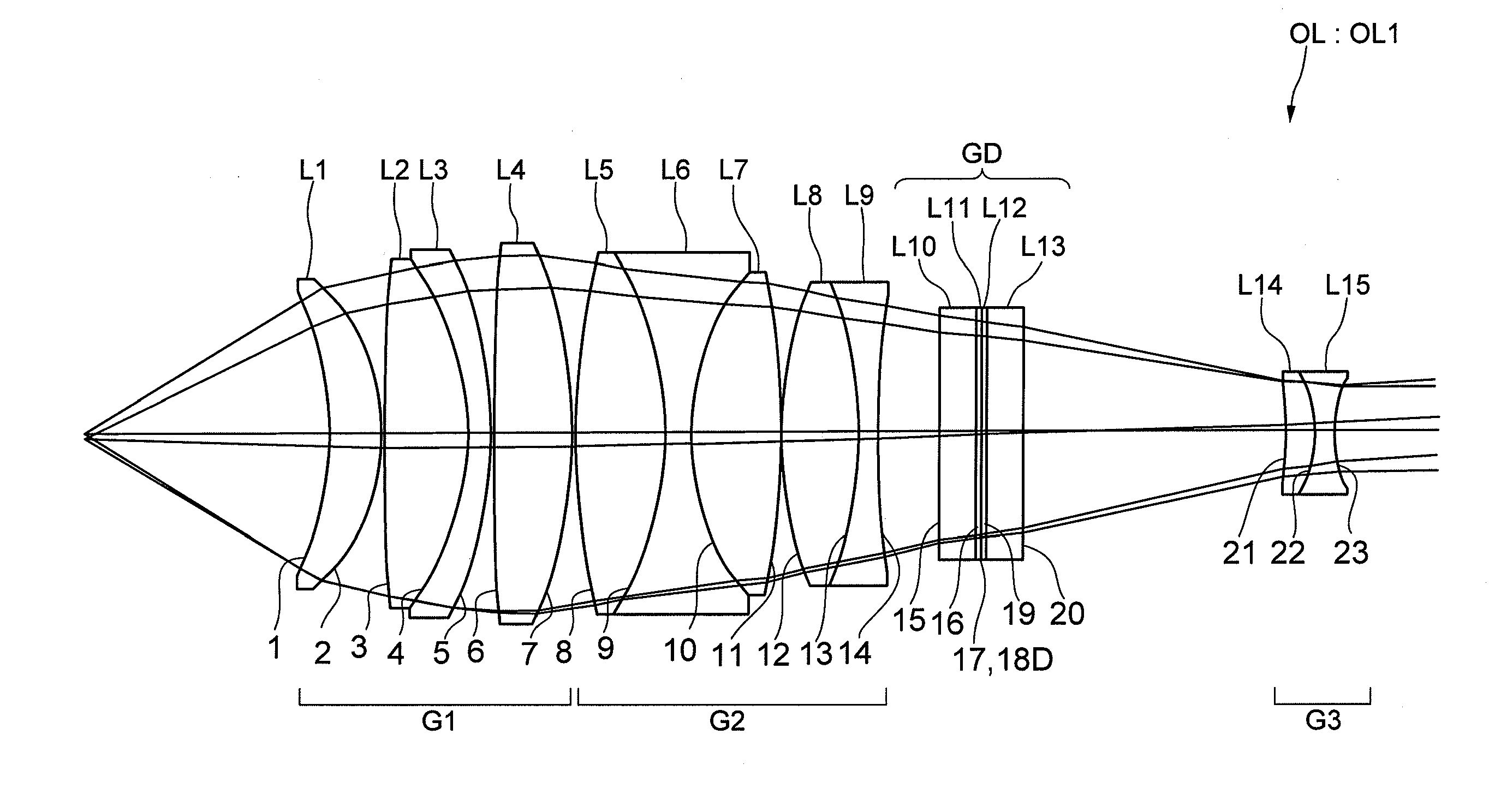
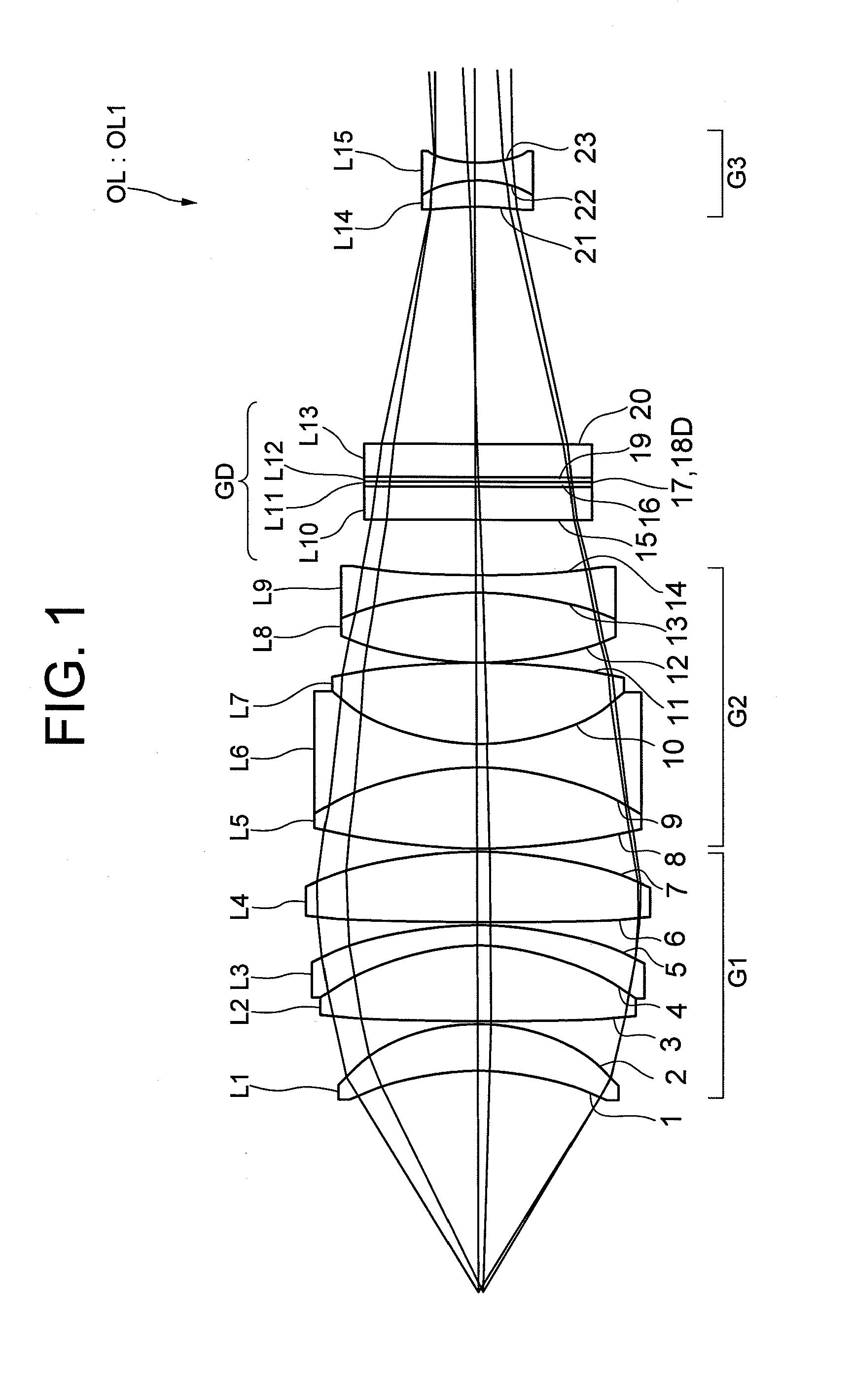
[0032]FIG. 1 used in the above explanation shows an objective lens OL according to Example 1 of the present invention. As described above, the objective lens OL1 includes, in order from an object side, a first lens group G1 having positive refractive power, a second lens group G2 having positive refractive power, and a third lens group G3 having negative refractive power, and a diffractive optical element GD is disposed between the second lens group G2 and the third lens group G3. The first lens group G1 is composed of a positive meniscus lens L1 having a concave surface facing the object side, a cemented lens constructed by a double convex positive lens L2 and a negative meniscus lens L3 having a concave surface facing the object side cemented in this order with each other, and a double convex positive lens L4. The second lens group G2 is composed of a cemented lens constructed by a double convex positive lens L5, a double concave negative lens L6 and a double convex positive lens ...

example 2

[0036]Then, an objective lens OL2 shown in FIG. 3 is explained as Example 2. The objective lens OL2 shown in FIG. 3 also includes, in order from an object side, a first lens group G1 having positive refractive power, a second lens group G2 having positive refractive power, and a third lens group G3 having negative refractive power, and a diffractive optical element GD is disposed between the second lens group G2 and the third lens group G3. The first lens group G1 is composed of a cemented lens constructed by a piano-concave negative lens L21 having a concave surface facing the object side and a piano-convex positive lens L22 having a convex surface facing an image side cemented in this order with each other, and a positive meniscus lens L23 having a concave surface facing the object side. The second lens group G2 is composed of a cemented lens constructed by a negative meniscus lens L24 having a convex surface facing the object side and a double convex positive lens L25 cemented in...

example 3

[0040]Moreover, an objective lens OL3 shown in FIG. 5 is explained as Example 3. The objective lens OL3 shown in FIG. 5 also includes, in order from an object side, a first lens group G1 having positive refractive power, a second lens group G2 having positive refractive power, and a third lens group G3 having negative refractive power, and a diffractive optical element GD is disposed between the second lens group G2 and the third lens group G3. The first lens group G1 is composed of a positive meniscus lens L41 having a concave surface facing the object side, a positive meniscus lens L42 having a concave surface facing the object side, a positive meniscus lens L43 having a concave surface facing the object side, and a cemented lens constructed by a double concave negative lens L44 and a double convex positive lens L45 cemented in this order with each other. The second lens group G2 is composed of a cemented lens constructed by a double convex positive lens L46, double concave negati...


PUM


Abstract

An objective lens OL includes, in order from an object, a first lens group G1 having positive refractive power, a second lens group G2 having positive refractive power, a diffractive optical element GD forming a diffractive optical surface D thereon, and a third lens group G3 having negative refractive power. The first lens group G1 includes at least one cemented lens and the most object side surface thereof forms a concave surface facing the object. The second lens group G2 includes at least one cemented lens. The third lens group G3 includes at least one cemented negative lens. In the objective lens OL, a principal ray crosses an optical axis between the second lens group G2 and the third lens group G3, and in the diffractive optical element GD, the diffractive optical surface D is disposed in the vicinity of the position where the principal ray crosses the optical axis.

Description

TECHNICAL FIELD[0001]The present invention relates to an objective lens used for an optical system such as a microscope.BACKGROUND ART[0002]In an observation using a microscope, it is necessary to observe a sample in a natural color, so that an objective lens with highly corrected chromatic aberration has been expected. Moreover, in order to make the handling of the sample easy, an objective lens keeping a working distance as long as possible has been expected. However, when a long working distance is to be secured, the object side focal length of the objective lens has to be long, and a negative lens group having strong refractive power has to be disposed to the image side, so that chromatic aberration naturally becomes worse. Accordingly, recently, there have been proposed various objective lenses using a diffractive optical element in order to highly correct chromatic aberration (see, for example, Japanese Patent Publication No. 3312057).[0003]However, the objective lens whose ch...

Claims


Application Information

Patent Timeline
Patent Type & Authority Applications(United States)
IPC IPC(8): G02B9/12G02B27/42
CPCG02B9/64G02B21/02G02B27/0056G02B27/42G02B27/4211
Inventor YOSHIDA, MIWAKO
Owner NIKON CORP
Why Eureka
Try Eureka