Fiber collimating lenses and method

a fiber and collimating lens technology, applied in the field of optical fiber collimating lenses, can solve the problems of affecting reliability, complicated packaging, toxic and expensive, etc., and achieve the effect of long working distance and large beam diameter

Inactive Publication Date: 2007-03-13
BEAMTEK
View PDF11 Cites 12 Cited by
  • Summary
  • Abstract
  • Description
  • Claims
  • Application Information

AI Technical Summary

Benefits of technology

[0014]The present invention provides a compact, inexpensive and rugged fiber collimating lens and lens array that achieve large beam diameters and provide long working distances.
[0015]This is accomplished by splicing a special single-mode fiber between a standard single-mode input fiber such as Corning SMF-28 and a GRIN fiber lens, typically quarter-pitch or slightly longer. The specialty fiber condenses the mode field diameter (MFD) of the beam in the input fiber into its smaller MFD. As a result, the fiber collimating lens provides greater beam expansion due to the larger divergence angle of the specialty fiber, which in turn provides longer working distances.

Problems solved by technology

The lens diameter (>1 mm) is a lot larger than the fiber diameter (125 microns), which complicates packaging and impacts reliability.
Furthermore, the GRIN lenses are made by an ion exchange method, which is usually toxic and expensive.
The only limiting factors are the amount of beam expansion and the length of the working distance that can be achieved.

Method used


Image

  • Fiber collimating lenses and method
  • Fiber collimating lenses and method
  • Fiber collimating lenses and method

Examples


embodiment 1

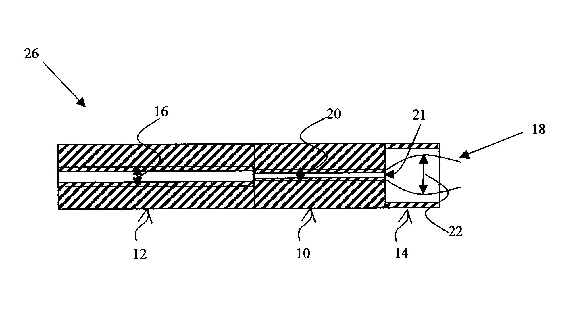
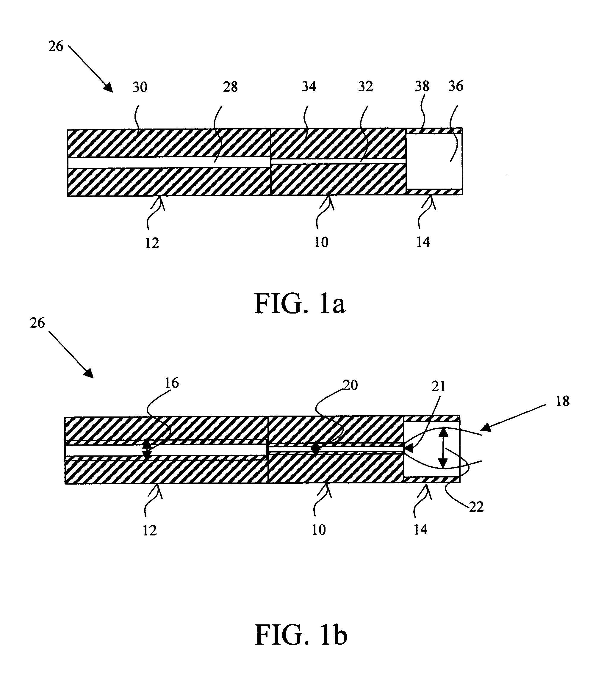
[0042]The specialty single mode fiber 10 (4 μm MFD at 1550 nm) is sandwiched between the input single mode fiber 12 (SMF-28 with MFD 10.4 μm at 1550 nm) and the graded index multimode fiber lens 14 (62.5 / 125). The quarter pitch length, beam waist, and maximum working distance are given in Table 1.

[0043]

TABLE 1ParametersEmbodiment 1ControlQuarter pitch length (μm)266266Beam waist diameter at5621.6quarter pitch length (μm)Maximum working distance (mm)1.780.18Beam waist diameter at maximum4017working distance (μm)

[0044]The specialty single mode fiber 10 (3.3 μm MFD at 1310 nm) is sandwiched between the input single mode fiber 12 (SMF-28 with MFD 9.2 μm at 1310 nm) and the graded index multimode fiber lens 14 (62.5 / 125). The quarter pitch length, beam waist, and maximum working distance are given in Table 2.

[0045]

TABLE 2ParametersEmbodiment 1ControlQuarter pitch length (μm)266266Beam waist diameter at57.420.6quarter pitch length (μm)Maximum working distance (mm)1.970.204Beam waist diame...

embodiment 2

[0046]A specialty single mode fiber 80 (4 μm MFD at 1550 nm) is sandwiched between a single mode input fiber 82 (SMF-28 with MFD 10.4 μm at 1550 nm) and a graded index multimode fiber lens 84 (100 / 140). As shown in FIG. 5 the outer diameter of the lens fiber 84 is a little bigger than the 125 μm standard diameter of the SMF fiber. The quarter pitch length, beam waist, and maximum working distance are given in Table 3.

[0047]

TABLE 3ParametersEmbodiment 1ControlQuarter pitch length (μm)404404Beam waist diameter at8632.8quarter pitch length (μm)Maximum working distance (mm)3.660.488Beam waist diameter at maximum60.624.4working distance (μm)

[0048]The specialty single mode fiber 80 (3.3 μm MFD at 1310 nm) is sandwiched between single mode input fiber 82 (SMF-28 with MFD 9.2 μm at 1310 nm) and graded index multimode fiber lens 84 (100 / 140). The quarter pitch length, beam waist, and maximum working distance are given in Table 4.

[0049]

TABLE 4ParametersEmbodiment 1ControlQuarter pitch length ...

embodiment 3

[0050]To further increase the working distance of the fiber collimating lens 26, the distal end of the GRIN fiber 14 can be formed with a convex surface 90 as shown in FIG. 6a. The convex surface can be formed by heat melting based on electric discharge, or chemical etching.

[0051]Alternately, a coreless fiber 92 having a uniform refractive index can be fused to the distal end of the GRIN fiber 14. The distal end of the coreless fiber is melted to form a hemispherical surface 94 by heating based on electric discharge, or chemical etching, as shown in FIG. 6b.


PUM


Abstract

A compact, inexpensive and rugged fiber collimating lens and lens array achieve large beam diameters and provide long working distances. A special single-mode fiber is inserted between a standard single-mode input fiber and a GRIN fiber lens, typically quarter-pitch or slightly longer. The specialty fiber condenses the mode field diameter (MFD) of the beam in the input fiber into its smaller MFD. As a result, the fiber collimating lens provides greater beam expansion due to the larger divergence angle of the specialty fiber, which in turn provides longer working distances.

Description

BACKGROUND OF THE INVENTION[0001]1. Field of the Invention[0002]This invention relates to optical fiber collimating lenses for coupling an optical beam in or out of optical communication components and devices, and more specifically to fiber collimating lenses that use a specialty single-mode fiber to expand and focus the light beam and provide long working distances.[0003]2. Description of the Related Art[0004]Graded refractive index (GRIN) lenses have been widely used in optical components and devices as collimating, focusing and coupling lenses. A GRIN lens has a refractive index whose value varies with radial distance from the axis of the lens. The refractive index of a square-law GRIN lens can be given by:n2(r)=n02[1−g2r2]  (1)where n0 is the refractive index on the axis of the lens, r is the radial distance from the central axis, and g is the focusing parameter. In the GRIN lens, rays follow sinusoidal paths until reaching the back surface of the lens. A light ray that has tra...

Claims


Application Information

Patent Timeline
Patent Type & Authority Patents(United States)
IPC IPC(8): G02B6/26G02B6/42G02B6/255G02B6/30G02B6/32H04B10/12
CPCG02B6/4206G02B6/32G02B6/262G02B6/2551G02B6/2552G02B6/30
Inventor JIANG, SHIBINLI, MAOHE
Owner BEAMTEK
Why Eureka
Try Eureka