Compact optical fiber coupler

a technology of optical fiber and coupler, applied in the field of compact optical fiber coupler, can solve the problems of increasing the sensitivity of signal loss to angular offset with beam diameter, macroscopic collimated lenses present limitations in miniaturizing devices or increasing interconnection density without increasing device or package size significantly, and fabricating lenses on the end of single modes. achieve the effect of high interconnection density

Inactive Publication Date: 2005-03-29
JDS UNIPHASE CORP
View PDF11 Cites 13 Cited by
  • Summary
  • Abstract
  • Description
  • Claims
  • Application Information

AI Technical Summary

Benefits of technology

FIG. 1 illustrates the benefits of the inventive optical coupler in forming a high interconnection density device 10. Optical signals arriving from waveguide 1 are transmitted to waveguide 2 after reflection of surface 13 in device 10. To avoid signal losses the optical power arriving from waveguide 1 must be efficiently coupled between device input port 11 and device output port 12. Light emitted by the waveguide 1 must be fully collected at output port 12 for re-transmission via waveguide 2 after reflection at surface 13. The inventive optical coupler modifies the free space propagation of light emitted by waveguide 1 and the collection of such light into waveguide 2 such that ports 11 and 12 may be considered object and image points separated by a working distance (WD) equal to the length, L, of segments 14 and segment 15, i.e. WD equals 2L .
As alpha approaches 0 the angle of incidence with respect to reflective surface 13 (alpha / 2) results in a desirable reduction in polarization dependent loss. If reflective surface 13 is an interference filter, the long working distance provides the additional benefit of reducing the angle of incidence, thus minimizing the potential polarization splitting, spectral shift characteristic of interference filters among several other signal degrading effects.

Problems solved by technology

The optical devices and interconnections in any route will result in signal losses, thus the signal power and signal to noise ratio of any optical signal can be expected to vary with the routing path.
However, the sensitivity of signal loss to angular offset increases with beam diameter.
However, the typical macroscopic collimated lenses present limitations in miniaturizing devices or increasing the interconnection density without increasing the device or package size considerably.
While several methods have been suggested for fabricating a lens on the end of a single mode optical fiber they are not suitable when there must be very low signal loss or a miniature device, such as optical cross-connect switches or multiplex / de-multiplex device.
However, these design either have significant disadvantages with respect to achieving a high interconnection density devices, for example the formation of an adequate lens either increases the diameter of the single mode fiber, or distorts the edge, thus making the subsequent alignment necessary to achieve low insertion loss difficult, or have a high return loss.
The additional components increase the complexity of assembly and result in additional signal loss from splice misalignment.
However, it has been found that such devices are not suitable in miniature devices because they cannot easily be aligned, due to irregularities in the surface shape at the fusion joint, and / or do not shape the exiting beam in a manner compatible with both low loss and a high-density of interconnection.
However, such configurations appear too difficult to manufacture without increasing or distorting the outer diameter, which is problematic in alignment and assembly.
Furthermore, such combinations suffer undesirable back reflection or return loss.

Method used


Image

  • Compact optical fiber coupler
  • Compact optical fiber coupler
  • Compact optical fiber coupler

Examples


Embodiment Construction

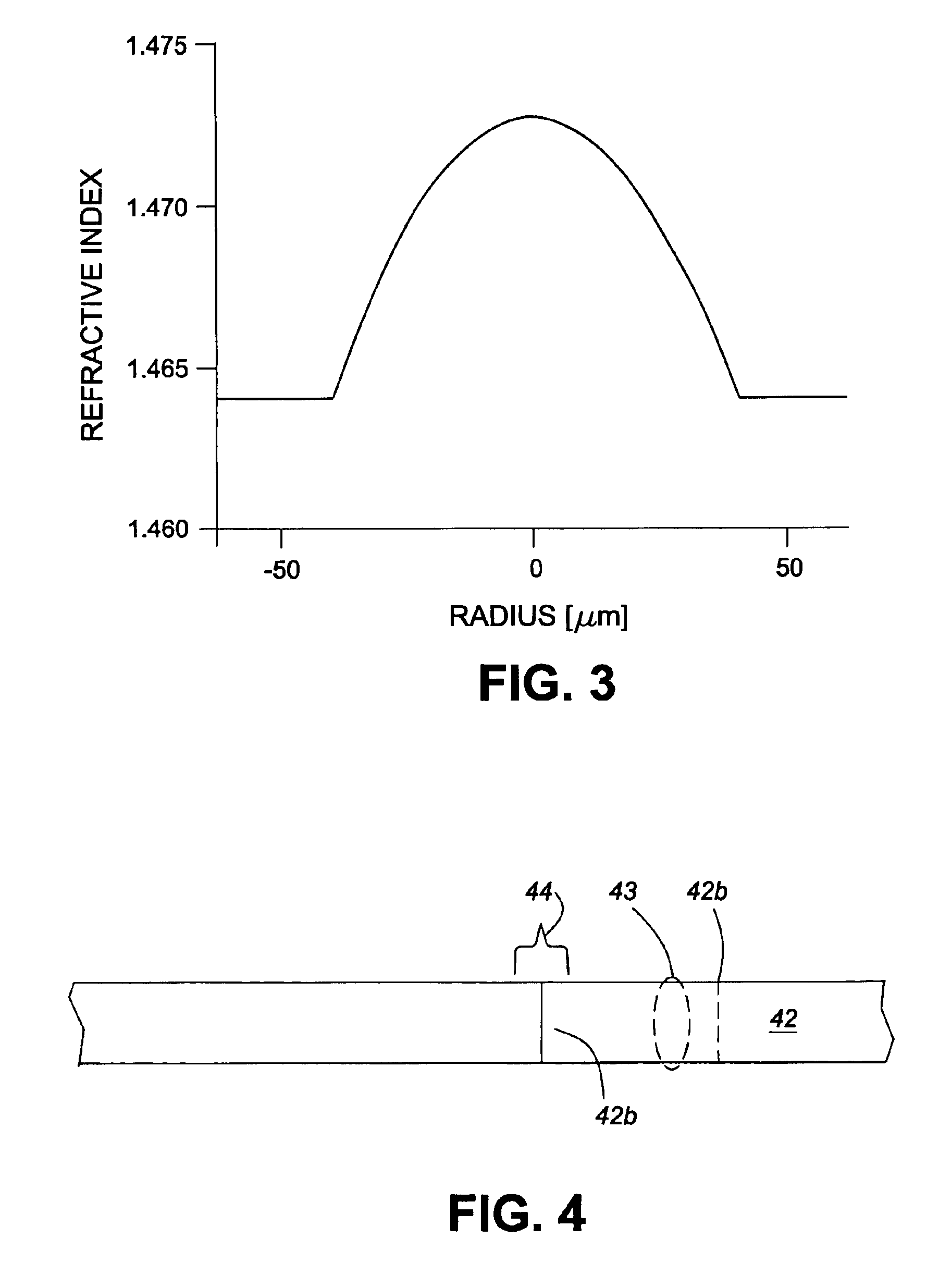
In order to achieve the long working distance, WD, between optical ports the gradient index fiber has a predetermined profile of refractive index, which is illustrated in FIG. 3.

FIG. 3 illustrates the preferred refractive index profile for the compact optical fiber coupler. The profile corresponds to equation 1:-

n(r)=n0[1−g2r2 / 2]

wherein g=2.7 / mm and n0=1.49 at a wavelength of 1.55 microns.

The gradient fiber is produced by conventional drawing of a doped fiber preform fabricated with the corresponding Ge / P-SiO2 glass composition profile. The total difference in index within the preform, which corresponds to the gradient in the fiber, is less than about 0.001. In the fiber core region, represented by the refractive index gradient, is preferably greater than about 70 to 80 microns. This gradient of refractive index and core diameter results in an optical coupler having a working distance of about 550 to 600 microns and a spot size of about 18 microns when the section of gradient index ...


PUM


Abstract

The inventive coupling device enables a high interconnection density of single mode optical fiber in active and passive devises used in a fiber optic telecommunication system. The coupling device comprise a micro-lens formed by terminating a single mode optical fibers with an optimized gradient index fiber, thus avoiding a significant increase in fiber diameter. The gradient index is optimized to provide a long working distance to the minimum spot size so that efficient coupling can be achieved in a free space interconnection between either multiple single mode fibers or a single mode fiber to a transmitting or receiving device.

Description

BACKGROUND OF INVENTIONIn an optical communications system optical signals may be transmitted in free space, but are generally transmitted over optical waveguides, typically optical fibers. Since optical fiber transmission offers tremendous bandwidth and transmission rate advances over the transmission of electrical signals, conversion to electrical signals are avoided as much as possible by active optical processing such as optical amplification, switching and routing. It is usually desirable to avoid conversion of the signal to an electrical signals until they reach the target destination, where they are converted back to electrical signals representing digital data, voice or images in various analog formats.In order to maximize the capacity of fiber optic communication systems many signal are simultaneously transmitted over the same fiber waveguides in a scheme known as wavelength division multiplexing or WIDM. In WDM each discrete signal may correspond to a different wavelength ...

Claims


Application Information

Patent Timeline
Patent Type & Authority Patents(United States)
IPC IPC(8): G02B6/26G02B6/255G02B6/36G02B6/35
CPCG02B6/2551G02B6/2552G02B6/262G02B6/3652G02B6/3582G02B6/3636G02B6/3512
Inventor DUELLI, MARKUSBLACK, LELAND SCOTTHALLOCK, ROBERT W.TAYLOR, ANDREW THOMAS
Owner JDS UNIPHASE CORP
Why Eureka
Try Eureka