
A waste cutting mechanism

A technology for cutting waste and waste, applied in the field of waste cutting mechanism, can solve the problems of increasing labor costs, inability to carry out continuous mold production, and increasing production costs.

Active Publication Date: 2017-12-19
TANGXIA BRANCH VISION TOOL & MOLD
View PDF5 Cites 0 Cited by
  • Summary
  • Abstract
  • Description
  • Claims
  • Application Information

AI Technical Summary

Problems solved by technology

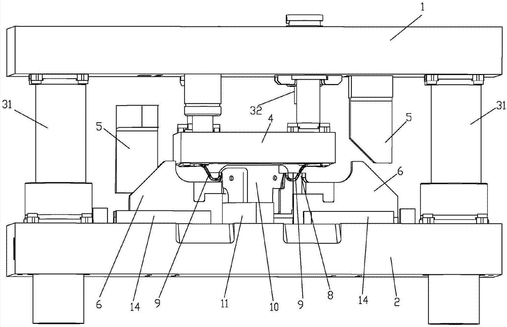
[0004] Although the above-mentioned waste material cutting mechanism can complete the cutting of the waste material 9 of the part 10 well, there are still problems: in actual production, after cutting the waste material 9, the part 10 needs to enter the next station for the next processing, such as punching and polishing etc., but in the existing waste cutting mechanism, due to the existence of the spacer 11, the scrap 9 of the part 10 cannot fall from the lower mold base 2 to the next station after being cut, and if the spacer 11 is removed, the part 10 cannot be fixed , it cannot be cut, so the existing waste cutting mechanism cannot realize the continuous die production of parts 10. When people in the field encounter this situation, they often choose to take out the parts 10 from the waste cutting mechanism by adding a manual simplex station. Entering the next station, because the manual simplex station requires workers to operate, the safety and production efficiency of production are greatly reduced. In addition, due to the increasing labor costs, the production cost is greatly increased
[0005] Based on the problem that the continuous die production cannot be carried out because the parts cannot be dropped in the existing waste cutting mechanism, it is urgent to improve the existing waste cutting mechanism

Method used


Image

  • A waste cutting mechanism
  • A waste cutting mechanism
  • A waste cutting mechanism

Examples


Embodiment Construction

[0028] The present invention will be further described in conjunction with the accompanying drawings and embodiments.

[0029] It should be noted that, unless otherwise specified, the front, back, left, and right directions in the following description are compatible with the middle, up, and down directions of the upper mold base and the lower mold base.

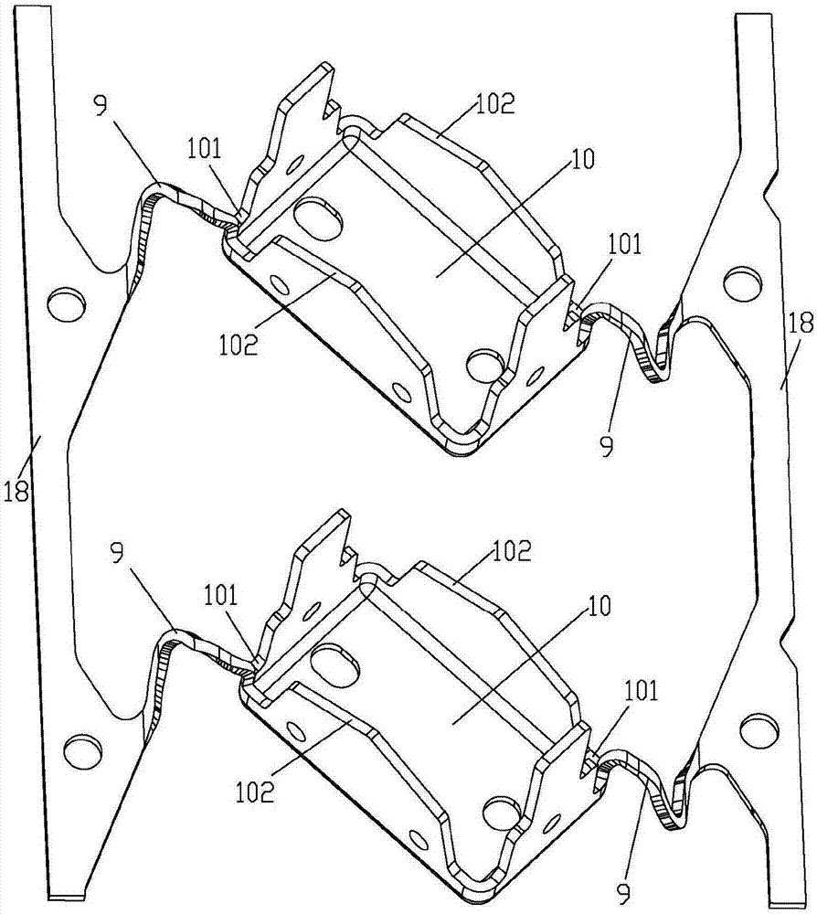
[0030] For ease of understanding, a schematic structural view of the part 10 is provided, as figure 2 As shown, the part 10 includes a part foot 102 and a part corner 101. During the processing of the part 10, residual waste 9 will inevitably be generated. One end of the waste 9 is connected to the part corner 101 of the part 10, and the other end is connected to the material tape 18 is connected, and the strip 18 drives the parts 10 to advance synchronously on the production line.

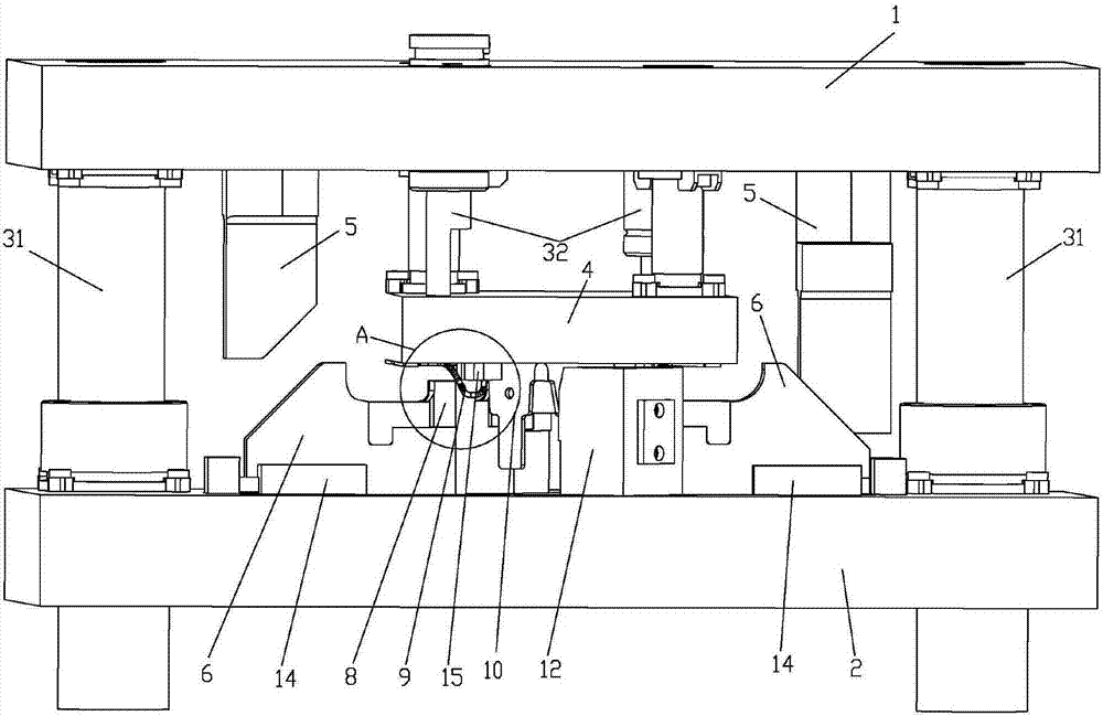
[0031] The waste material cutting mechanism of the embodiment of the present invention, as Figure 3-8 As shown, the waste cutting mechanism...


PUM


Abstract

The invention relates to the technical field of hardware stamping molds, in particular to a scrap cutting mechanism, which comprises an upper mold seat and a lower mold seat. The upper mold seat is connected with a stripper plate with upper mold cutter bits, and is also connected with shovel bases; slide blocks and limited structures are arranged on the lower mold seat; lower mold cutter bits are arranged on the slide blocks; the upper mold cutter bits are provided with notches; and bearing pieces and through holes are also arranged on the lower mold seat. According to the scrap cutting mechanism provided by the invention, when the upper mold seat moves downwards, the stripper plate, the bearing pieces and the notches close to a parts and cooperatively fix the parts in a three-dimensional direction; the upper mold seat continuously moves downwards along with the lower mold seat, and scraps of the parts are cut through the cooperative action of the upper mold cutter bits and the lower mold cutter bits; the upper mold seat stops moving downwards but moves upwards, the stripper plate, the bearing pieces and the notches are far away from the parts, and the parts is fallen into a next work station from one through hole in a free falling way under the action of gravity so as to be processed in the next work process, so that the continuous mold production of the parts is realized.

Description

technical field [0001] The invention relates to the technical field of metal stamping dies, in particular to a waste cutting mechanism. Background technique [0002] The continuous mold widely used in the electronic device and automobile industry is composed of multiple stations, and each station is connected in sequence to complete different processes, and a series of different stampings can be completed in one stroke of the punching machine, such as: forming, scrap cutting , Blanking, punching, etc. Among them, the reason why there is a waste cutting station is that some waste materials connected to the part will be left during the forming process of the part. [0003] Cut waste mechanism in prior art, as figure 1 As shown, it includes an upper mold base 1, a guide post 31 and a lower mold base 2 connected in sequence, the waste material 9 is connected to the part 10, and the bottom surface of the upper mold base 1 is connected with a spring for limiting the upward movem...

Claims


Application Information

Patent Timeline
Patent Type & Authority Patents(China)
IPC IPC(8): B21D28/14B21D43/00
CPCB21D28/14B21D43/003
Inventor 姚小春王安学刘晓龙王丽芝罗忠涛
Owner TANGXIA BRANCH VISION TOOL & MOLD
Learn More