Eureka AIR delivers breakthrough ideas for toughest innovation challenges, trusted by R&D personnel around the world.

Method and device for seismic source location in a microseismic monitoring system

A technology of seismic source positioning and monitoring system, which is applied in the field of geophysical exploration in wells, and can solve the problems that the monitoring results are difficult to meet the needs and the amount of calculation is large.

Active Publication Date: 2018-09-04
BC P INC CHINA NAT PETROLEUM CORP +1
View PDF9 Cites 0 Cited by
  • Summary
  • Abstract
  • Description
  • Claims
  • Application Information

AI Technical Summary

Problems solved by technology

The positioning speed of this method depends on the monitoring accuracy. The higher the monitoring accuracy, the denser the grid division required, and the calculation amount will be very large. When the monitoring accuracy is low, the calculation speed can be improved, but the monitoring results often difficult to meet needs

Method used


Image

  • Method and device for seismic source location in a microseismic monitoring system
  • Method and device for seismic source location in a microseismic monitoring system
  • Method and device for seismic source location in a microseismic monitoring system

Examples


Embodiment Construction

[0058] In order to make the purpose, technical solutions, and advantages of the embodiments of the present application clearer, the embodiments of the present application will be further described in detail below in conjunction with the embodiments and the accompanying drawings. Here, the schematic embodiments and descriptions of the embodiments of the present application are used to explain the embodiments of the present application, but are not intended to limit the embodiments of the present application.

[0059] The specific implementation manners of the embodiments of the present application will be further described in detail below in conjunction with the accompanying drawings.

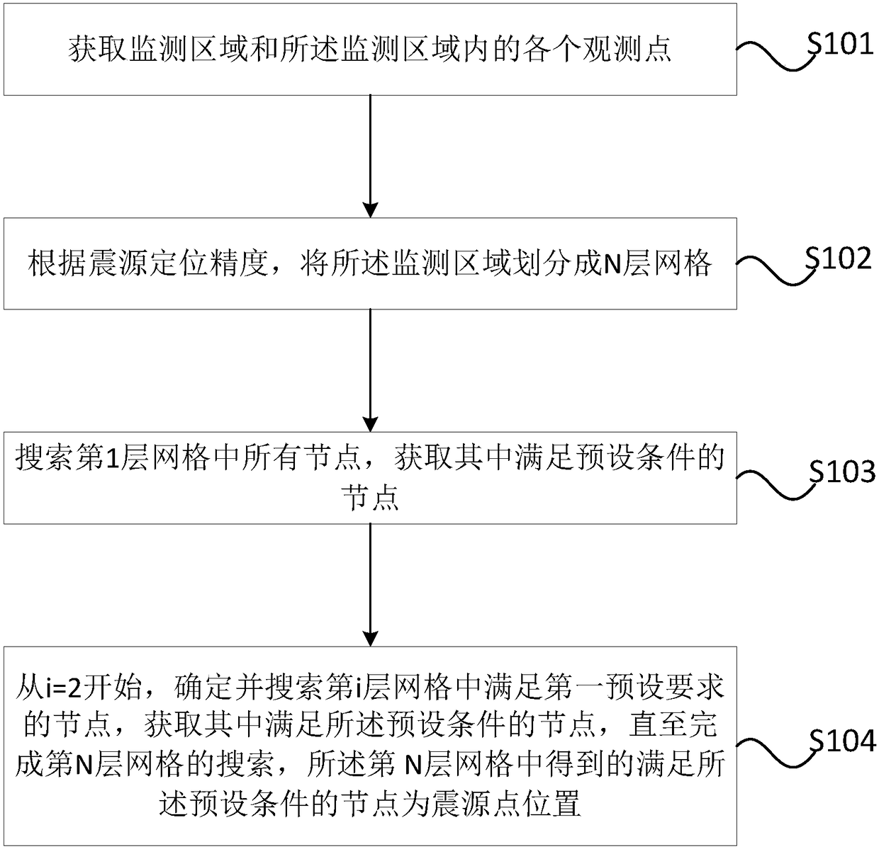
[0060] Such as figure 1 Shown is a schematic flowchart of a method for locating an earthquake source in a microseismic monitoring system. Such as figure 1 As shown, a method for source location in a microseismic monitoring system may include:

[0061] S101. Obtain a monitoring area and each o...


PUM


Abstract

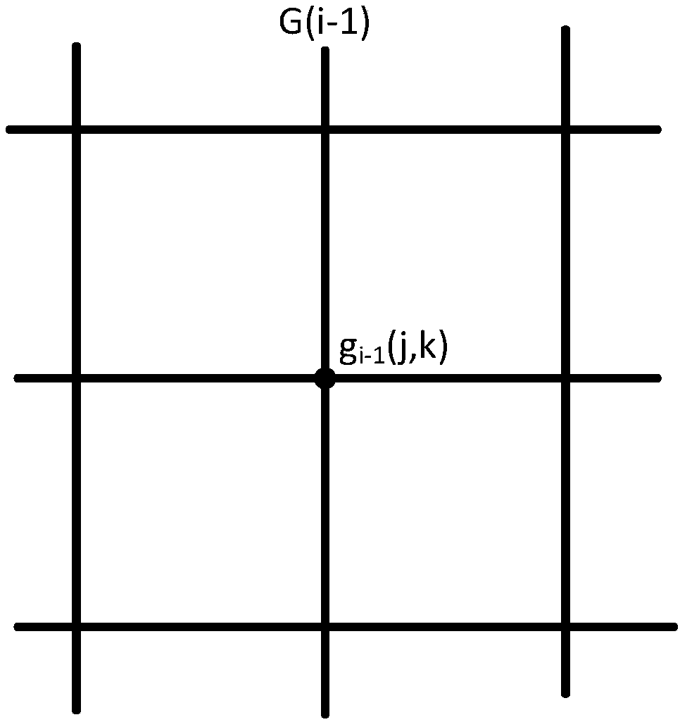
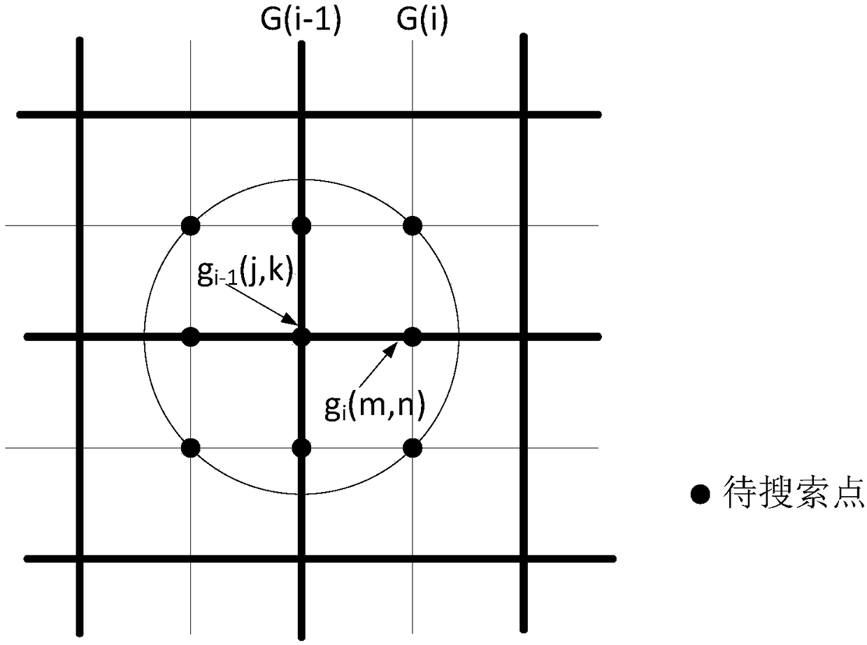
Embodiments of the present application provide a method and device for locating seismic sources in a microseismic monitoring system. The method includes: obtaining a monitoring area and each observation point in the monitoring area; according to the source positioning accuracy, dividing the monitoring area into N-layer grids, wherein the side length of the grid unit of the i-th layer grid is D / 2i-1, i=1,...N, D is the initial side length of the grid unit; search all the nodes in the grid of the first layer, and obtain the nodes that meet the preset conditions; start from i=2, determine and Search for nodes in the i-th layer grid that meet the first preset requirements, and obtain nodes that meet the preset conditions, until the search of the N-th layer grid is completed, and the nodes obtained in the N-th layer grid meet the The node of the preset condition is the location of the source point. The embodiment of the present application realizes high-precision and precise microseismic source positioning with a small amount of calculation.

Description

technical field [0001] The present application relates to the technical field of borehole geophysical prospecting, in particular to a method and device for locating seismic sources in a microseismic monitoring system. Background technique [0002] Microseismic monitoring technology is a geophysical technology that monitors the impact, effect and underground state of production activities by observing and analyzing small seismic events generated in production activities. It is used in hydraulic fracturing fracture monitoring, oilfield safety monitoring, oilfield dynamic monitoring and Fields such as mine safety play an important role. The key to microseismic monitoring technology is to accurately determine the location of the earthquake source. [0003] In the current microseismic source location method based on the forward modeling model, the location of the microseismic source is determined by dividing the monitoring area into uniform grids and searching nodes one by one. ...

Claims


Application Information

Patent Timeline
Patent Type & Authority Patents(China)
IPC IPC(8): G01V1/28
CPCG01V1/28G01V2210/6222G01V2210/123G01V1/288G01V1/005G01V1/30
Inventor 金其虎刘聪伟李彦鹏李飞徐刚储仿东
Owner BC P INC CHINA NAT PETROLEUM CORP
Why Eureka
Eureka Blog
Learn More