Axial split-phase internal stator permanent magnet biased magnetic suspension switched reluctance flywheel motor

A technology of switched reluctance and permanent magnet bias, applied in the direction of magnetic attraction or thrust holding devices, electrical components, electromechanical devices, etc., can solve the problem of limited critical speed of flywheel, difficult integration of motors, and difficult integrated design, etc. To reduce the difficulty of suspension control, improve the axial utilization rate and the critical speed of the flywheel, and improve the suspension performance and operational reliability

Active Publication Date: 2017-02-08
NANJING INST OF TECH
View PDF5 Cites 20 Cited by
  • Summary
  • Abstract
  • Description
  • Claims
  • Application Information

AI Technical Summary

Problems solved by technology

The proposal of these new structures has effectively weakened the problem of electromagnetic coupling. However, when used in flywheel batteries, there are still many shortcomings, such as the double stator structure is not easy to integrate the design of the motor and flywheel, and there are serious temperature rise and heat dissipation in the inner and outer stator windings. The problem is that the efficiency of the motor is low under high-speed operation; the axial length of the motor is still long due to the hybrid rotor structure, and the critical speed of the flywheel is limited; the hybrid stator and the permanent magnet bias structure adopt an external stator structure, the motor is not easy to integrate with the flywheel, and The permanent magnet is on the outer stator side, which consumes more permanent magnet materials, and the cost performance is not high
[0004] To sum up, it can be seen that when the existing maglev switched reluctance motor is used in the field of flywheel batteries, there are still deficiencies in structure, mechanism and function. Therefore, it is necessary to design a new structure in combination with the specific application of flywheel batteries.

Method used


Image

  • Axial split-phase internal stator permanent magnet biased magnetic suspension switched reluctance flywheel motor
  • Axial split-phase internal stator permanent magnet biased magnetic suspension switched reluctance flywheel motor
  • Axial split-phase internal stator permanent magnet biased magnetic suspension switched reluctance flywheel motor

Examples


Embodiment Construction

[0020] In order to deepen the understanding of the present invention, the present invention will be described in further detail below in conjunction with the accompanying drawings and embodiments, which are only used to explain the present invention and do not limit the protection scope of the present invention.

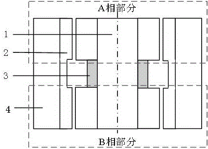
[0021] like figure 1 As shown, the present invention is an axial phase split inner stator permanent magnet bias magnetic levitation switched reluctance flywheel motor, comprising an inner stator 1, an outer rotor 2, a permanent magnet ring 3, and a flywheel 4, and the outer rotor 2 is laminated and packaged Inside the flywheel 4, that is to say, the flywheel 4 is fixed on the outside of the outer rotor 2 of the motor. The flywheel and the rotor are combined into one whole, and the inner stator core and the outer rotor core are divided into m segments along the axis according to the number of phases. figure 1 The special case of m=2 is given, which are A-phase part an...


PUM


Abstract

The invention provides an axial split-phase internal stator permanent magnet biased magnetic suspension switched reluctance flywheel motor comprising an external rotor, a flywheel and an internal stator. The external rotor is packaged at the internal side of the flywheel in a laminating way. An internal stator iron core and an external rotor iron core are divided into m segments along the axis according to the phase number. The internal side of each segment of external rotor is equidistantly provided with 12 rotor poles along the circumference. The internal stator iron core is provided with 8 narrow tooth main magnetic poles and 4 wide tooth suspension poles. Main pole control coils and suspension control coils are respectively wound on the narrow tooth main magnetic poles and the wide tooth suspension poles. The coils on each narrow tooth main magnetic pole are interconnected in series to form a main pole winding. Every two of the control coils on each segment of wide tooth suspension pole are connected in series so as to form two sets of suspension windings in an orthogonal direction. The size of the system can be reduced and the critical speed of rotation can be enhanced; the suspension supporting loss can be reduced and the operation efficiency can be enhanced; and the stator poles are separately provided with the suspension poles, the main magnetic poles and magnetic isolating rings so that the control algorithm can be simplified and the suspension performance and the decoupling effect can be enhanced.

Description

technical field [0001] The invention belongs to the technical field of magnetic levitation switched reluctance motors, and in particular relates to a magnetic levitation switched reluctance flywheel motor with axial phase split inner stator permanent magnet bias magnetic levitation switched reluctance. Background technique [0002] Energy shortage and environmental pollution are major problems faced by countries all over the world. The development of energy-saving and environmentally friendly electric vehicles to reduce fuel consumption and exhaust pollution is an effective way to alleviate this problem. Batteries are the power source of electric vehicles and one of the key factors restricting the development of electric vehicles. Flywheel batteries are highly valued at home and abroad for their advantages such as high specific energy, high specific power, fast charging, and environmental protection. However, there are still many technologies Difficulties restrict its practi...

Claims


Application Information

Patent Timeline
Patent Type & Authority Applications(China)
IPC IPC(8): H02N15/00H02K7/02H02K1/17H02K1/12
CPCY02E60/16H02N15/00H02K1/12H02K1/17H02K7/025
Inventor 朱志莹孙玉坤
Owner NANJING INST OF TECH
Why Eureka
Try Eureka