Media transport in rotor shaft

A technology of rotor and hollow shaft, which is applied in the field of medium conveying system in the rotor shaft, which can solve the problems of excessive weight of the rotor shaft, excessive medium volume, and limited low weight.

Active Publication Date: 2017-02-22
THYSSENKRUPP PRESTA TECCENTER AG
View PDF12 Cites 7 Cited by
  • Summary
  • Abstract
  • Description
  • Claims
  • Application Information

AI Technical Summary

Problems solved by technology

In this respect, the disadvantages of the above-mentioned prior art are the excessively large medium volume in the rotor shaft cavity, the excessive weight of the rotor shaft and / or the limited possibility of optimizing the low weight

Method used


Image

  • Media transport in rotor shaft
  • Media transport in rotor shaft
  • Media transport in rotor shaft

Examples


Embodiment Construction

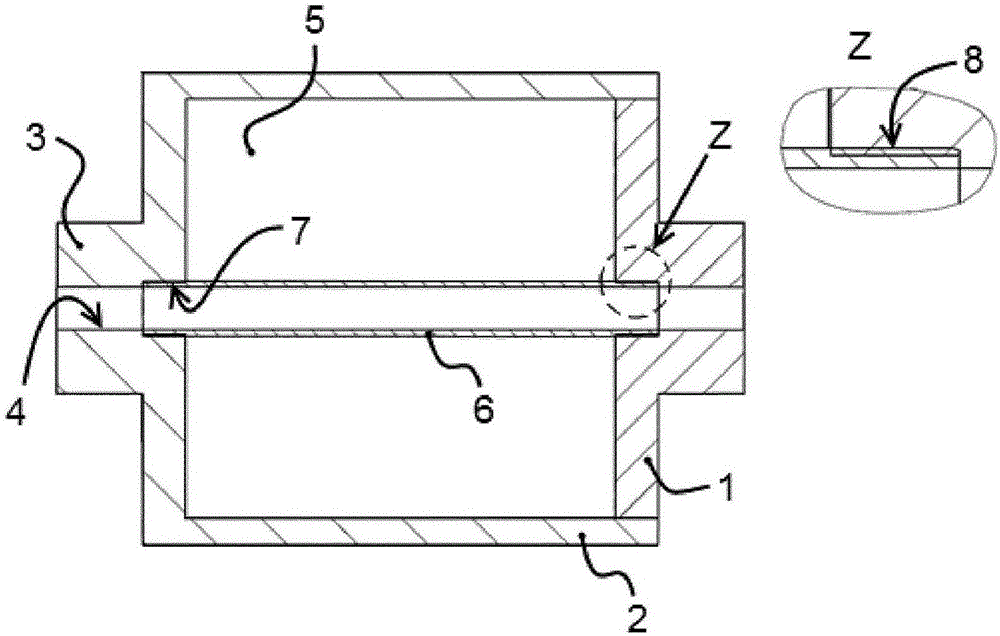
[0024] figure 1A rotationally symmetrical rotor hollow shaft for a rotor of an electric machine is shown. The rotor hollow shaft comprises a cylindrical barrel 2 which is closed on both sides by end flanges 1 made of steel, wherein in each case a journal is positioned on the end flange 1 3. Here, the journal may be formed on the end flange in an inseparable form, or may be a separate part held on the end flange. In this case, coaxial access holes 4 are provided on the two journals, which, as long as they are not closed, provide access to the shaft cavity 5 surrounded by the cylindrical barrel 2 . As a guide element, a hollow cylindrical tube 6 is provided, consisting of a soft material such as aluminium or plastic, the outer diameter of which can be seen being smaller than the inner diameter of the shaft cavity 5 . On the side of the shaft chamber 5 , the tube piece 6 is pressed on both sides into a screwed annular receptacle 7 , which emerges around the inlet opening 4 . ...


PUM


Abstract

The invention relates to a hollow rotor shaft for the rotor of an electrical machine, having a cylindrical jacket, which terminates at both ends with end flanges, wherein a main journal is formed at each of the end flanges, wherein an access bore is provided at least in one of the main journals, said access bore forming access to the shaft cavity that is surrounded by a cylindrical jacket, wherein a conducting element is provided, which fits into the access bore such that the conducting element seals off from the shaft cavity and which leads through the surrounding shaft cavity to the other main journal, into which the conducting element likewise fits such that the conducting element seals off from the shaft cavity, wherein the conducting element allows a liquid or gaseous medium to be conducted through.

Description

technical field [0001] The invention relates to a hollow rotor shaft for a rotor of an electric machine, wherein the hollow rotor shaft comprises a cylindrical barrel closed on both sides by end flanges, wherein on the end flanges in each case there are positioned A journal, and wherein at least one of the end flanges, in particular in the journal, is provided with a coaxial access hole which provides access for the medium to the shaft cavity surrounded by the cylindrical barrel. The invention also relates to a rotor with a rotor hollow shaft and a corresponding electric machine, wherein the rotor hollow shaft is equipped with a lamination assembly. Background technique [0002] It is evident, for example, from DE 42 40 045 C1 and DE 203 07 198 U1 that such rotor hollow shafts have been known for a long time and are used in various places where the lightest possible construction is sought. If the rotor hollow shaft is "assembled" from several parts, in particular from the c...

Claims


Application Information

Patent Timeline
Patent Type & Authority Applications(China)
IPC IPC(8): H02K9/10H02K9/19
CPCH02K9/10H02K9/197H02K7/003H02K9/193H02K1/32
Inventor 克里斯蒂安·奎绍丹尼尔·保罗
Owner THYSSENKRUPP PRESTA TECCENTER AG
Why Eureka
Try Eureka