Power factor improving converter and power supply device including power factor improving converter

一种功率因数改善、电源装置的技术,应用在输出功率的转换装置、直流功率输入变换为直流功率输出、不可逆的交流功率输入变换为直流功率输出等方向,能够解决噪音滤波器大型化、共模电流大、小型化效果没有提升空间等问题,达到减少共模电流、较少共模噪声、滤波器小型化的效果

Inactive Publication Date: 2017-05-24
SHINDENGEN ELECTRIC MFG CO LTD
View PDF8 Cites 0 Cited by
  • Summary
  • Abstract
  • Description
  • Claims
  • Application Information

AI Technical Summary

Problems solved by technology

[0020] Conventional power factor improvement converters, even if they try to achieve miniaturization by increasing the switching frequency, there is still a problem that there is no room for improvement in the miniaturization effect due to the increase in component losses.
[0021] In addition, there is a problem of increasing the size of the noise filter due to the large common mode current

Method used


Image

  • Power factor improving converter and power supply device including power factor improving converter
  • Power factor improving converter and power supply device including power factor improving converter
  • Power factor improving converter and power supply device including power factor improving converter

Examples


Embodiment 1

[0055] (Constitution of Embodiment 1)

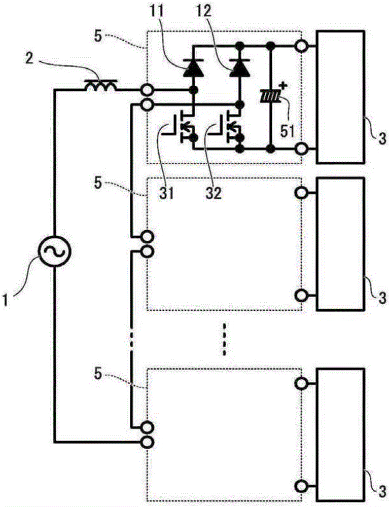
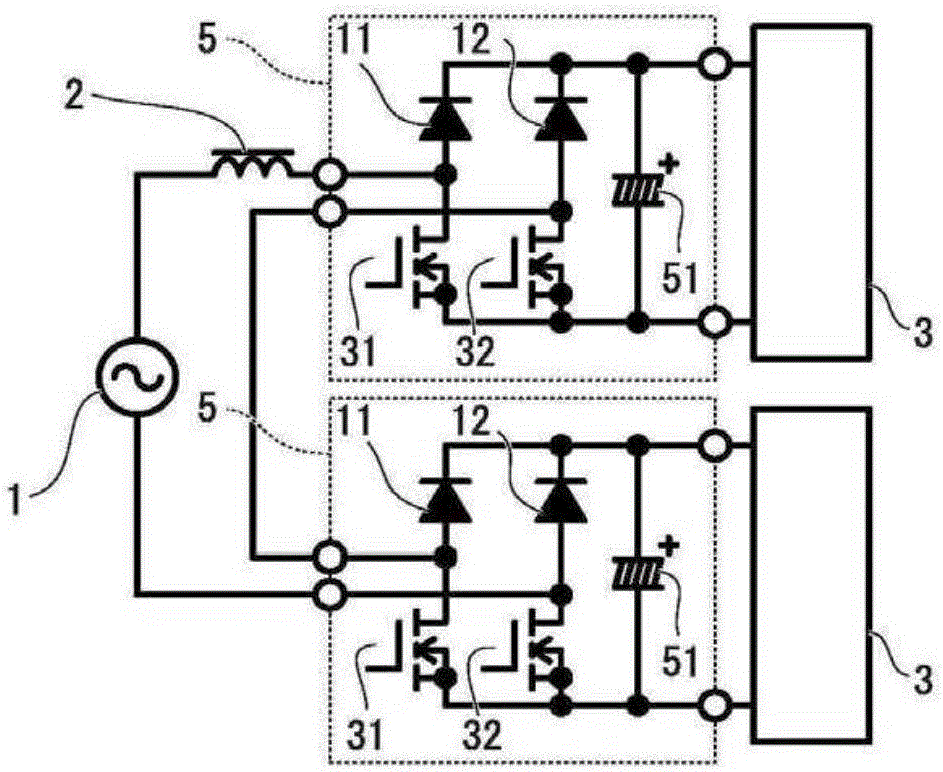
[0056] figure 2 An embodiment of the present invention in which the number n of levels is 3 is shown in . The converter is composed of an AC power source 1 , a choke 2 , two circuit modules 5 , and a load 3 connected to an output terminal of each circuit module 5 .

[0057] Each circuit module 5 includes: a first series circuit in which a diode 11 and a MOSFET 31 are connected in series; a second series circuit in which a diode 12 and a MOSFET 32 are connected in series; and a capacitor 51 . The drain of MOSFET 31 is connected to the anode of diode 11 , and the drain of MOSFET 32 is connected to the anode of diode 12 . One input terminal is connected to a connection point between the diode 11 and the MOSFET 31 , and the other input terminal is connected to a connection point between the diode 12 and the MOSFET 32 . The cathode of the diode 11 and the cathode of the diode 12 are connected to one end of the capacitor 51, the source of ...

Embodiment 2

[0076] (Constitution of Embodiment 2)

[0077] Figure 10 An embodiment of the present invention in which the number n of levels is four is shown in . The converter is composed of an AC power source 1 , a choke 2 , three circuit modules 5 , and a load 3 connected to an output terminal of each circuit module 5 .

[0078] Each circuit module 5 includes: a first series circuit in which a diode 11 and a MOSFET 31 are connected in series; a second series circuit in which a diode 12 and a MOSFET 32 are connected in series; and a capacitor 51 . The drain of MOSFET 31 is connected to the anode of diode 11 , and the drain of MOSFET 32 is connected to the anode of diode 12 . One input terminal is connected to a connection point between the diode 11 and the MOSFET 31 , and the other input terminal is connected to a connection point between the diode 12 and the MOSFET 32 . The cathode of the diode 11 and the cathode of the diode 12 are connected to one end of the capacitor 51, the sour...

Embodiment 3

[0099] (Constitution of Embodiment 3)

[0100] Embodiment three is: as Figure 12 As shown in the circuit, as a load, the primary side of the full-bridge converter 6 (hereinafter referred to as converter 6) is respectively connected to the figure 2 The circuit modules 5 in the shown circuit are connected, and the outputs of the converters 6 are connected to each other and then connected to the load 3 .

[0101] In each converter 6, the input of the bridge circuit composed of MOSFET33, MOSFET34, MOSFET35 and MOSFET36 is connected with the output terminal of each circuit module 5, the output of the bridge circuit is connected with the primary coil of transformer 61, and the output terminal of transformer 61 The secondary coil is connected to a rectifier circuit including diode 13 , diode 14 , diode 15 , and diode 16 , and the output of the rectifier circuit is connected to a smoothing circuit including resistor 8 and capacitor 52 .

[0102] (operation of embodiment three)

...


PUM


Abstract

The technical problem addressed by the present invention is solved by providing a plurality of circuit blocks, each circuit block including a first series circuit that includes a first diode and a first MOSFET, a second series circuit that includes a second diode and a second MOSFET, and a capacitor, wherein the output terminals are connected to the first series circuit, the second series circuit, and both ends of the capacitor. The input terminals of the circuit blocks are connected in series, and an AC power supply is connected to the interconnected input terminals via a choke.

Description

technical field [0001] The present invention relates to the application of multilevel power converter technology to non-isolated power factor improving converters, especially related to cascaded multilevel (Cascade Multicell) type multilevel converters. Background technique [0002] Conventionally, a method using a step-up chopper circuit has been widely known as a power factor improving converter. Figure 15 The circuit diagram of this method is shown in , the diode (Diode) 21, diode 22, diode 23, and diode 24 are connected by a bridge (Bridge), and an AC current 1 is connected as an input, and a choke (Chock) 2 and a current resistor (Chock) 2 are connected as an output. A series circuit of MOSFET37. A series circuit of a diode 25 and a capacitor (Condenser) 54 is connected between the source and the drain of the MOFET 37 , and the load 3 is connected to both ends of the capacitor 54 . [0003] Since this power factor improving converter takes the current from the choke 2...

Claims


Application Information

Patent Timeline
Patent Type & Authority Applications(China)
IPC IPC(8): H02M7/12
CPCH02M1/4225H02M1/4233H02M3/285H02M7/25Y02B70/10Y02P80/10H02M1/007H02M1/0074H02M1/0085H02M1/08H02M1/42H02M3/33523
Inventor 芳贺浩之
Owner SHINDENGEN ELECTRIC MFG CO LTD
Why Eureka
Try Eureka